

Agitating Ball Mill
a technology agitating roller, which is applied in the field of agitating ball mill, can solve problems such as wear or other impediments, and achieve the effect of improving the effect of the gap guard according to the invention
- Summary
- Abstract
- Description
- Claims
- Application Information
AI Technical Summary
Benefits of technology
Problems solved by technology
Method used
Image

Examples
Embodiment Construction
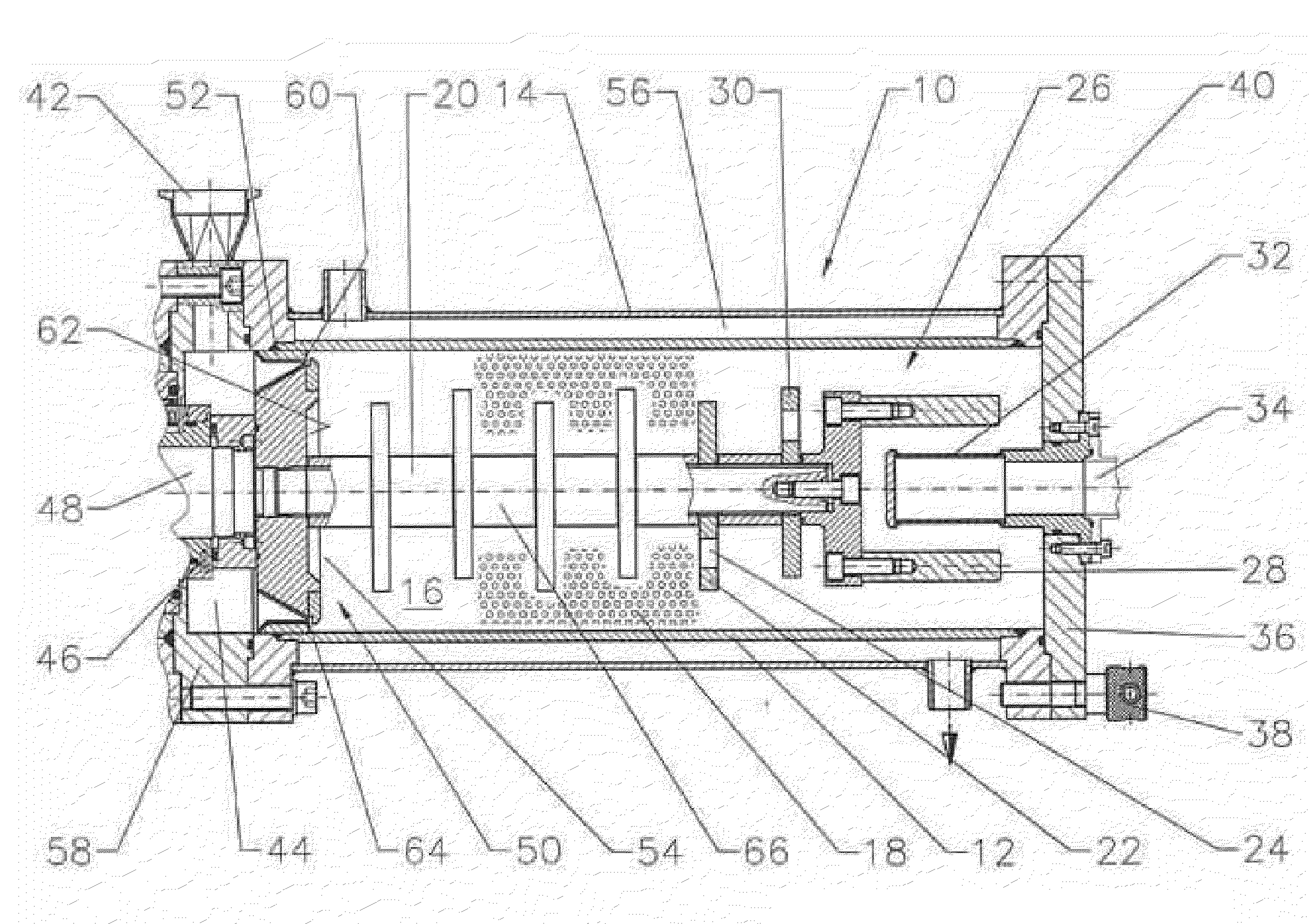
[0027]FIG. 1 shows an agitating ball mill 10 with a comminution vessel 12 which is surrounded by a cooling jacket 14. Comminution media 18 is located in the comminution chamber 16 which is purely shown in a certain region of the comminution chamber for demonstration. In the comminution chamber itself is located the agitating shaft 20 on which the comminution discs 22 with holes 24 are placed. The agitating shaft is put into rotation by a drive which is not shown. To separate the comminution media 18 from the product which is introduced into the comminution chamber, a pre-classifier 26 which can consist of a cage-like construction with a plurality of bars 28 and at least one disc 30 arranged at a close distance to the cage and provided with holes is seated at the free end of the agitating shaft 20. In the exemplary embodiment of FIG. 1 a separating device in form of a screen 32 is arranged downstream of the pre-classifier in terms of flow.
[0028]The product leaves the comminution cham...
PUM
 Abstract
Description
Claims
Application Information