Beam projection systems and methods

a beam projection and beam technology, applied in the field of beam projection systems and methods, can solve the problems of loss of efficiency, increased lens size, and small object size,

Inactive Publication Date: 2010-07-01
LUXIM CORP
View PDF59 Cites 21 Cited by
  • Summary
  • Abstract
  • Description
  • Claims
  • Application Information

AI Technical Summary

Benefits of technology

[0060]FIG. 15A is a schematic layout of an optical trai

Problems solved by technology

A related issue is that if the beam angle (DImage/SImage) is small, the object size is also small (DObject).
In most elliptical systems, a divergent beam leaves the aperture, which means increasing the object distance increases the size of the lens or causes overfill of the lens and a resulting loss in efficiency.
Because of the conservation of Etendue shrinking, the area increases in illumination beam angle, which increases the lens size, or reduces collection efficiency.
However, the small elliptical reflector is not practical due to the physical extent of the source and th

Method used


Image

  • Beam projection systems and methods
  • Beam projection systems and methods
  • Beam projection systems and methods

Examples


Embodiment Construction

[0071]While the present invention is open to various modifications and alternative constructions, the embodiments shown in the drawings are described herein as example embodiments.

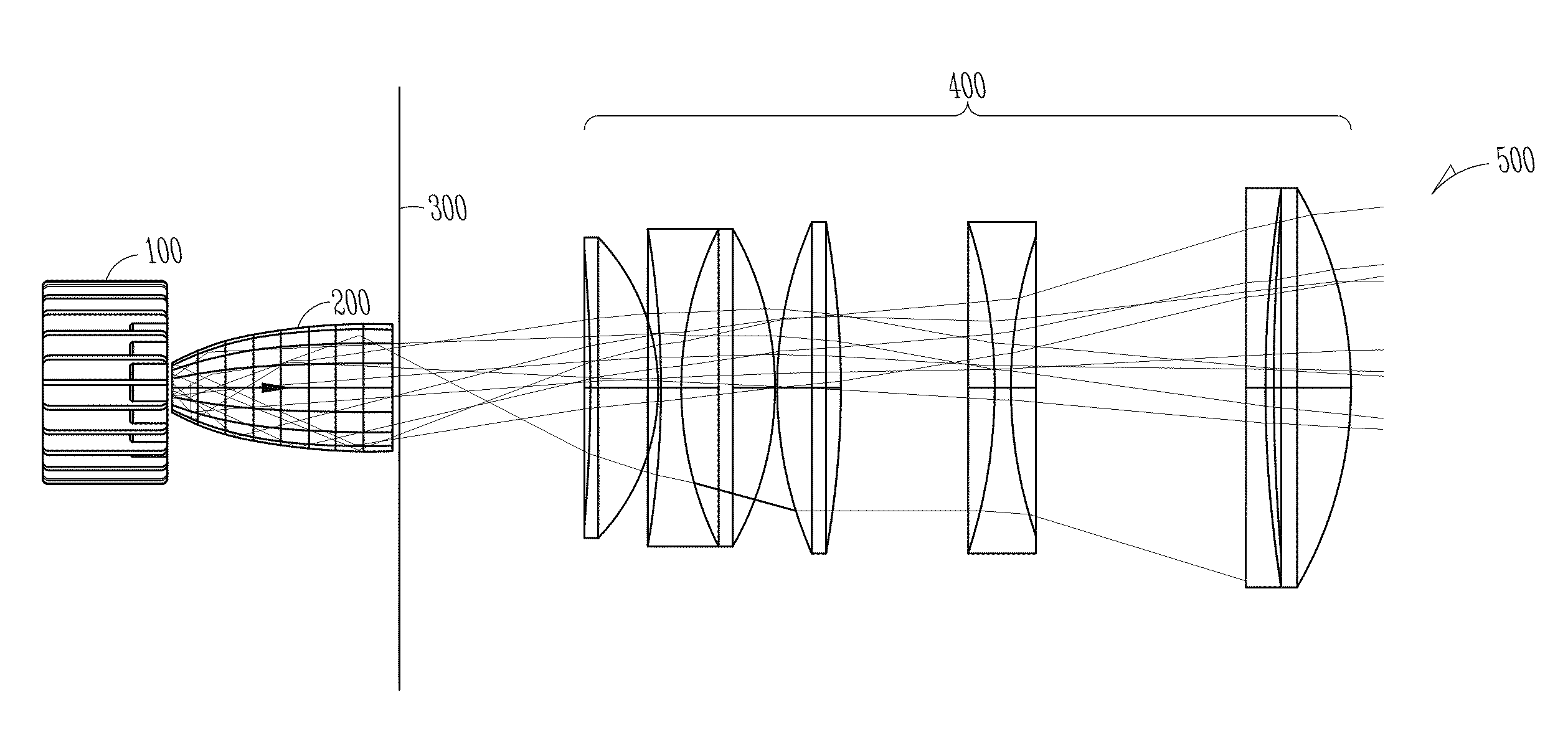
[0072]With reference to FIG. 2, a schematic layout of an example embodiment is shown to include a directional light source 100, a non-imaging optic 200 (also referred to herein as a NIO or non-imaging optical element), an aperture 300, an imaging lens 400, and a resulting projected beam 500. FIG. 3A is a cross-section and schematic view of a directional light source 150 according to another example embodiment. In a specific example embodiment, the directional light source may be the directional light source 100 of FIG. 2. In other example embodiments, the directional light source 150 may be used in the schematic layout shown in FIG. 2 or in any of the other beam projection and optical systems and layouts described herein. In the example of FIG. 3A, the directional light source may have a lamp body 102 form...


PUM


Abstract

Throughput efficiency of an optical system is enhanced by using a directional light source coupled to a non-imaging optical element matched to a size and acceptance angle of an imaging lens. In various embodiments, a beam projection system and accompanying method are described that include a lamp body formed from a dielectric material. A bulb, placed adjacent to the lamp body, has a fill that forms a plasma when RF power is coupled to the fill from the lamp body. An optical train is optically coupled to the bulb to transform light generated by the plasma. The optical train includes a non-imaging optical element, an aperture, and at least one imaging lens element.

Description

RELATED APPLICATION[0001]This application claims priority benefit to U.S. Provisional Patent Application Ser. No. 61 / 142,033 entitled, “BEAM PROJECTION SYSTEMS AND METHODS,” filed Dec. 31, 2008, which is hereby incorporated by reference in its entirety.FIELD OF THE INVENTION[0002]The present invention relates to optical systems for image projection applications. The scope of the invention includes light generation, collection, and imaging. Relevant applications include, for example, entertainment lighting, architectural lighting, security search lights, and exhibit lighting among others.[0003]The following two architectures are examples that are used in spotlighting systems: elliptical reflector) lens systems (see FIG. 1A) and retro-reflector condenser lens systems (see FIG. 1B). A primary goal of each of these systems is to deliver light from the source to the spot as efficiently as possible. A secondary goal is to manage the brightness uniformity, color uniformity, and edge defini...

Claims


Application Information

Patent Timeline
IPC IPC(8): G03B21/20G03B21/28
CPCG03B21/2026G03B21/208G02B19/0047G02B19/0028
Inventor MCGETTIGAN, ANTHONY D.DUELLI, MARKUSPRADHAN, APURBA
Owner LUXIM CORP
Why Eureka
Try Eureka