
Encoding device, encoding method, recording medium, and image processing apparatus

Inactive Publication Date: 2010-07-08
SONY CORP
View PDF6 Cites 20 Cited by
  • Summary
  • Abstract
  • Description
  • Claims
  • Application Information

AI Technical Summary

Benefits of technology

[0012]Incidentally, with the image processing apparatus 1S thus configured, encoding according to the DPCM processing is executed. This DPCM processing is simple encoding processing, and accordingly, there has been a possibility of the image data BL read out from the memory 4 and decoded markedly deteriorating. That is to say, the method described in Japanese Patent No. 3918263 can encode image data for each processing block that is small block increments using simple processing, but includes a problem in that deterioration in the image data results.
[0013]It has been found to be desirable to provide an encoding device, an encoding method, a recording medium, and an image processing apparatus, whereby image data is encoded for each small processing block using simple processing, and also deterioration in this image data is prevented.
[0022]According to the above configurations, a bit stream can be generated using a color difference signal bit stream in which the image quality does not deteriorate most with a range wherein the code amount of a luminance signal bit stream and the code amount of a color difference signal bit stream, which are actually used, are equal to or smaller than a fixed code amount. Thus, the present invention can realize an encoding device, an encoding method, a recording medium, and an image processing apparatus, whereby image data is encoded for each small processing block using simple processing, and also deterioration in this image data is prevented.

Problems solved by technology

That is to say, the method described in Japanese Patent No. 3918263 can encode image data for each processing block that is small block increments using simple processing, but includes a problem in that deterioration in the image data results.

Method used


Image

  • Encoding device, encoding method, recording medium, and image processing apparatus
  • Encoding device, encoding method, recording medium, and image processing apparatus
  • Encoding device, encoding method, recording medium, and image processing apparatus

Examples


embodiment

1. Embodiment

1-1. Configuration of Image Processing Apparatus

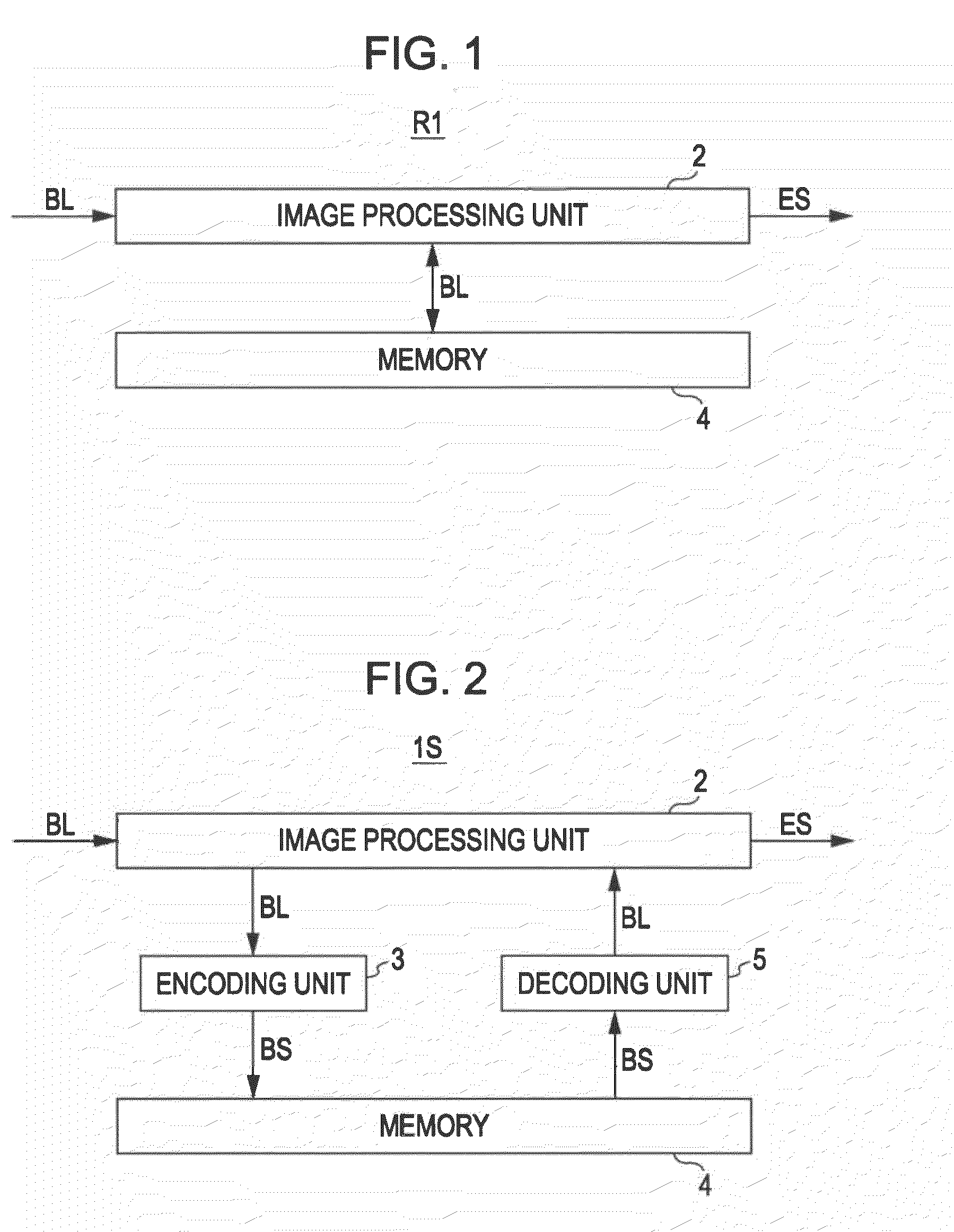
[0067]Item 1 indicates an image processing apparatus as a whole. Note that the portions corresponding to the related art shown in FIGS. 1 through 4B are denoted with the same reference numerals.

[0068]An image processing unit 2 subjects image data BL supplied externally to various types of image processing such as encoding processing, editing processing, or the like to generate a processing stream ES, and supplies this to an external device which is not shown.

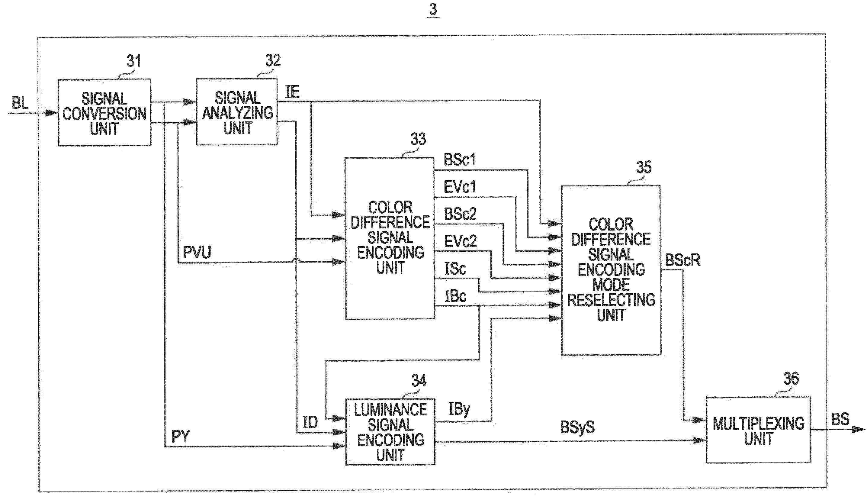
[0069]The image processing unit 2 supplies image data BL to be referenced later in an encoding unit 3 at the time of image processing. The encoding unit 3 subjects the image data BL to encoding processing (the details will be described later) to generate a bit stream BS, and supplies this to memory 4. Here, the memory 4 is configured so as to read out and write the image data BL in increments of bus transfer (e.g., 128 bytes).

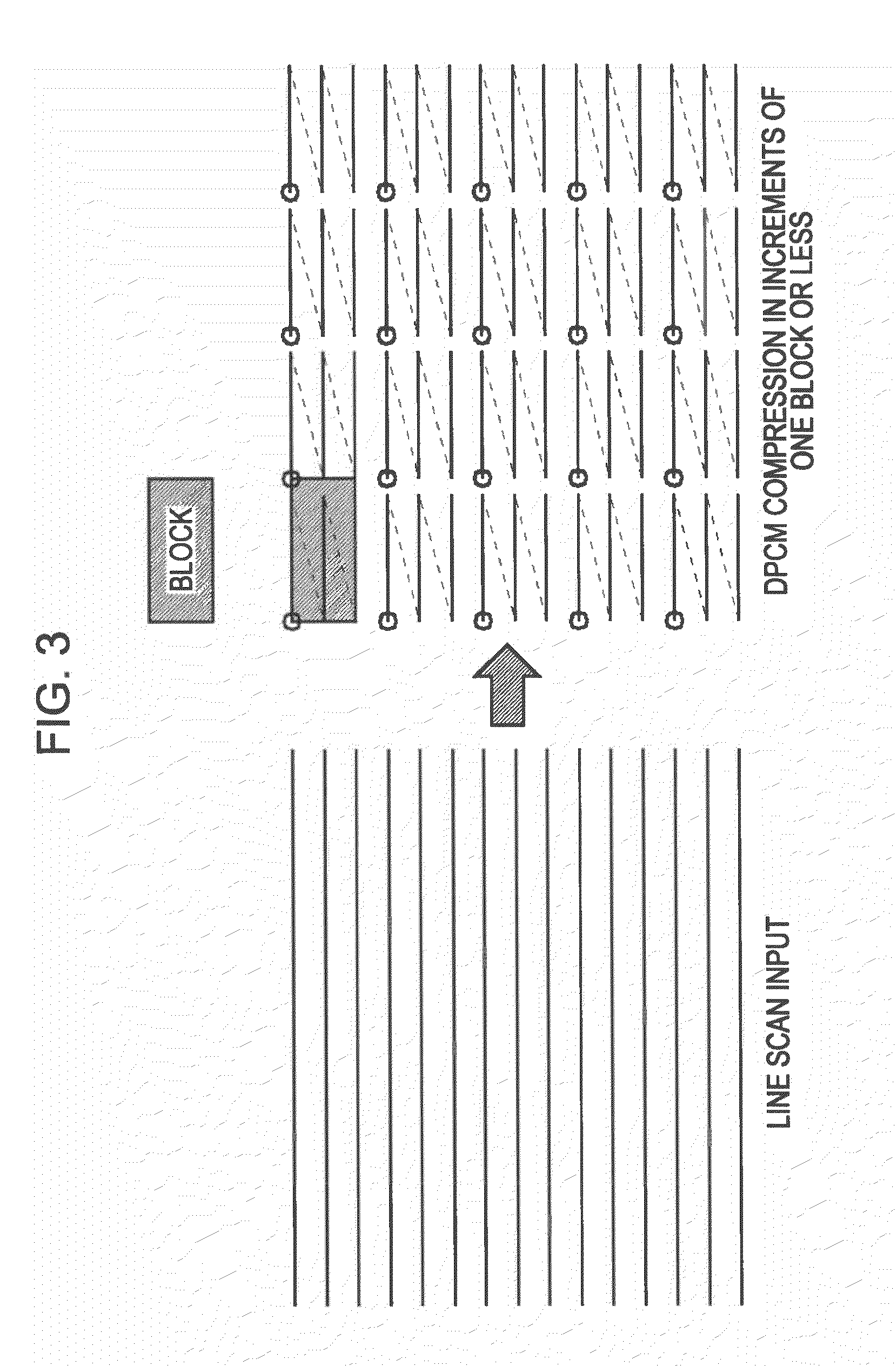
[0070]As shown in FIG. 6, if we say that th...


PUM


Abstract

An encoding device includes: a color-difference signal encoding unit for encoding a color-difference signal for each processing block in multiple color-difference signal encoding modes to generate multiple color-difference signal bit streams; a color-difference mode selecting unit for selecting a color-difference signal encoding mode from the multiple color-difference signal encoding modes; a luminance signal encoding unit for calculating luminance target code amount by subtracting the code amount of the encoded color-difference signal bit stream from fixed code amount, and encoding a luminance signal to generate a luminance signal bit stream; a color-difference reselecting unit for selecting the color-difference signal encoding mode corresponding to the color-difference signal bit stream having the code amount not greater than the fixed code amount, and small deterioration as to the color-difference signal; and a multiplexing unit for multiplexing the luminance signal bit stream, and the encoded color-difference signal bit stream to generate a bit stream.

Description

BACKGROUND OF THE INVENTION[0001]1. Field of the Invention[0002]The present invention relates to an encoding device, an encoding method, a recording medium, and an image processing apparatus, and is preferably applied to an image processing apparatus such as an encoder or the like which encodes image data in accordance with an encoding method, for example, such as MPEG (Moving Picture Experts Group) or the like.[0003]2. Description of the Related Art[0004]Heretofore, a technique has been widely used wherein image data is encoded by an encoder to be recorded or distributed, and is decoded by a decoder at the time of displaying an image thereof. In recent years, increased resolution and increased frame rates of image data has led to an increase in the information volume of this image data. Therefore, with image processing apparatuses, a great amount of image data has to be handled within a certain period of time despite restricted resources such as memory, computing power, and so fort...

Claims


Application Information

Patent Timeline
IPC IPC(8): G06K9/36H03M7/30H04N1/41H04N11/04H04N19/00H04N19/12H04N19/126H04N19/134H04N19/136H04N19/137H04N19/14H04N19/147H04N19/15H04N19/176H04N19/186H04N19/189H04N19/196H04N19/34H04N19/423H04N19/50H04N19/61H04N19/635H04N19/85H04N19/91
CPCH04N19/176H04N19/119H04N19/15H04N19/115H04N19/436H04N19/124H04N19/91H04N19/14H04N19/186H04N19/593
Inventor SHIMAUCHI, KAZUHIROWADA, YUJIIKEDA, HIROSHI
Owner SONY CORP
Learn More