Illumination device, display device, and light guide plate

a technology of light guide plate and display device, which is applied in the direction of fixed installation, lighting and heating apparatus, instruments, etc., can solve the problems of degrading the strength of the light guide block as a combination, and achieve the effects of reducing light leakage, sufficient luminance, and excellent uniformity

Active Publication Date: 2010-08-26
SHARP KK
View PDF22 Cites 27 Cited by
  • Summary
  • Abstract
  • Description
  • Claims
  • Application Information

AI Technical Summary

Benefits of technology

[0029]As mentioned above, the illumination device can retain its strength as a combination of light guide blocks while reducing leakage of light into an adjacent area. Therefore, the foregoing configuration can realize sufficient luminance and excellent uniformity, and can give a sturdy display device high in strength of the illumination device. Further, since the display device includes the illumination device, the display device can attain the second object together with the first object.
[0030]Further, according to the foregoing configuration, since the display device includes the foregoing configuration, the display device can be made thinner, and even in the case of an increase in light-emitting area, the display device can realize sufficient luminance and excellent uniformity in luminance. Moreover, a display device capable of adjusting the luminance of each illumination region for higher image quality can be provided.

Problems solved by technology

However, the more the thickness of the joint section between the light guide blocks is reduced, the more the strength of the light guide blocks as a combination is degraded.

Method used


Image

  • Illumination device, display device, and light guide plate
  • Illumination device, display device, and light guide plate
  • Illumination device, display device, and light guide plate

Examples


embodiment 1

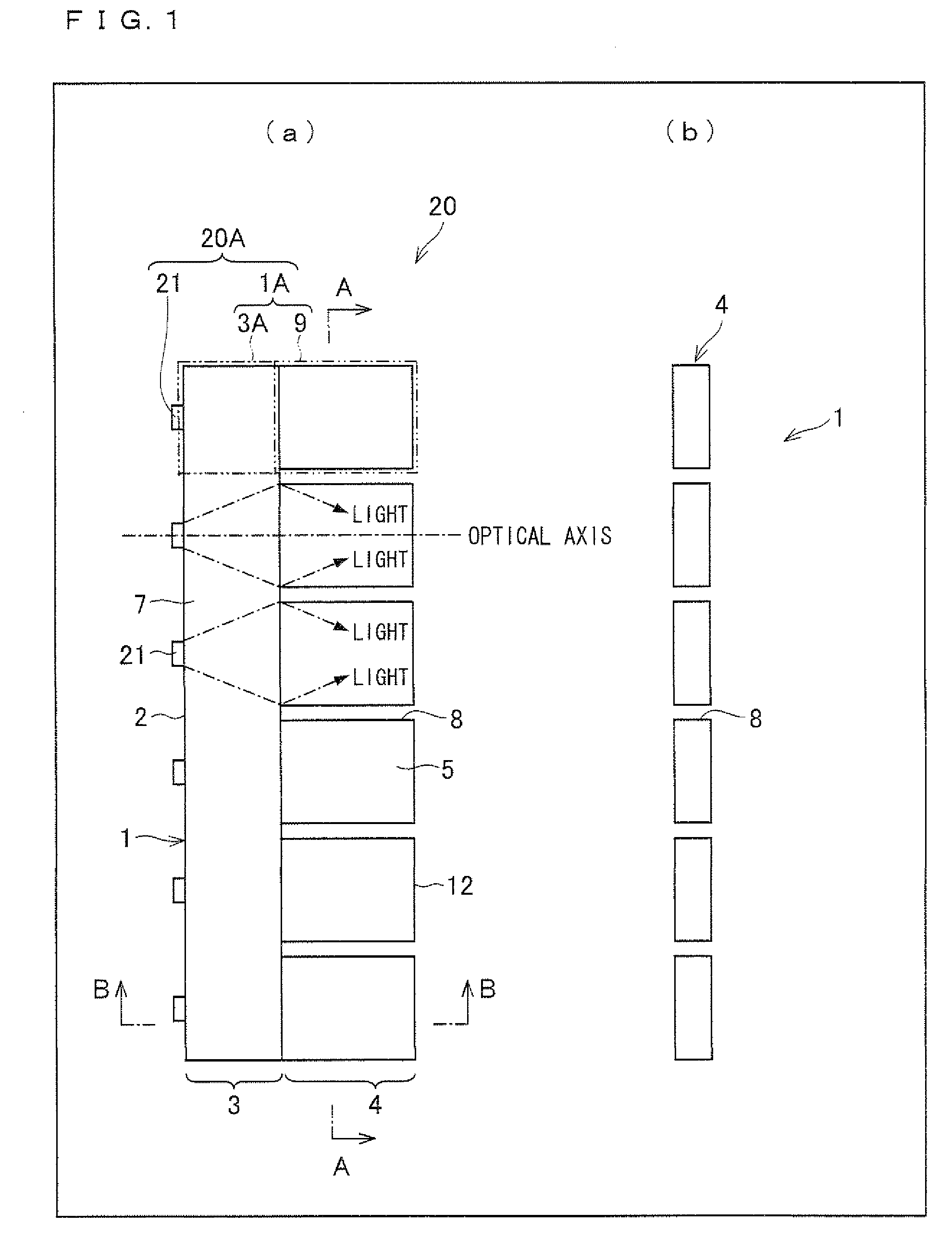
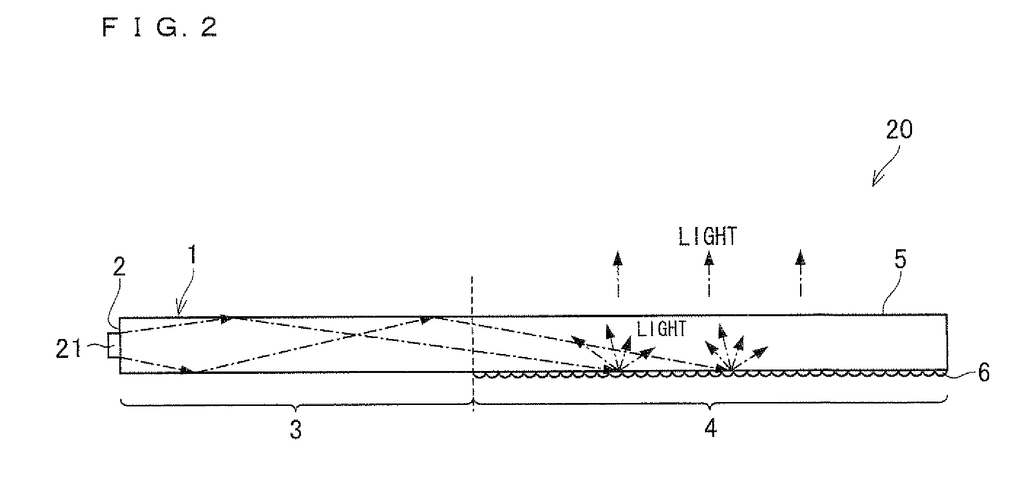
[0154]FIG. 1 shows (a) a plan view schematically showing the configuration of a light source unit in accordance with the present embodiment and (b) a cross-sectional view of a light guide plate of the light source unit taken along the line A-A of (a) of FIG. 1. FIG. 2 is a cross-sectional view of the light source unit taken along the line B-B of (a) of FIG. 1.

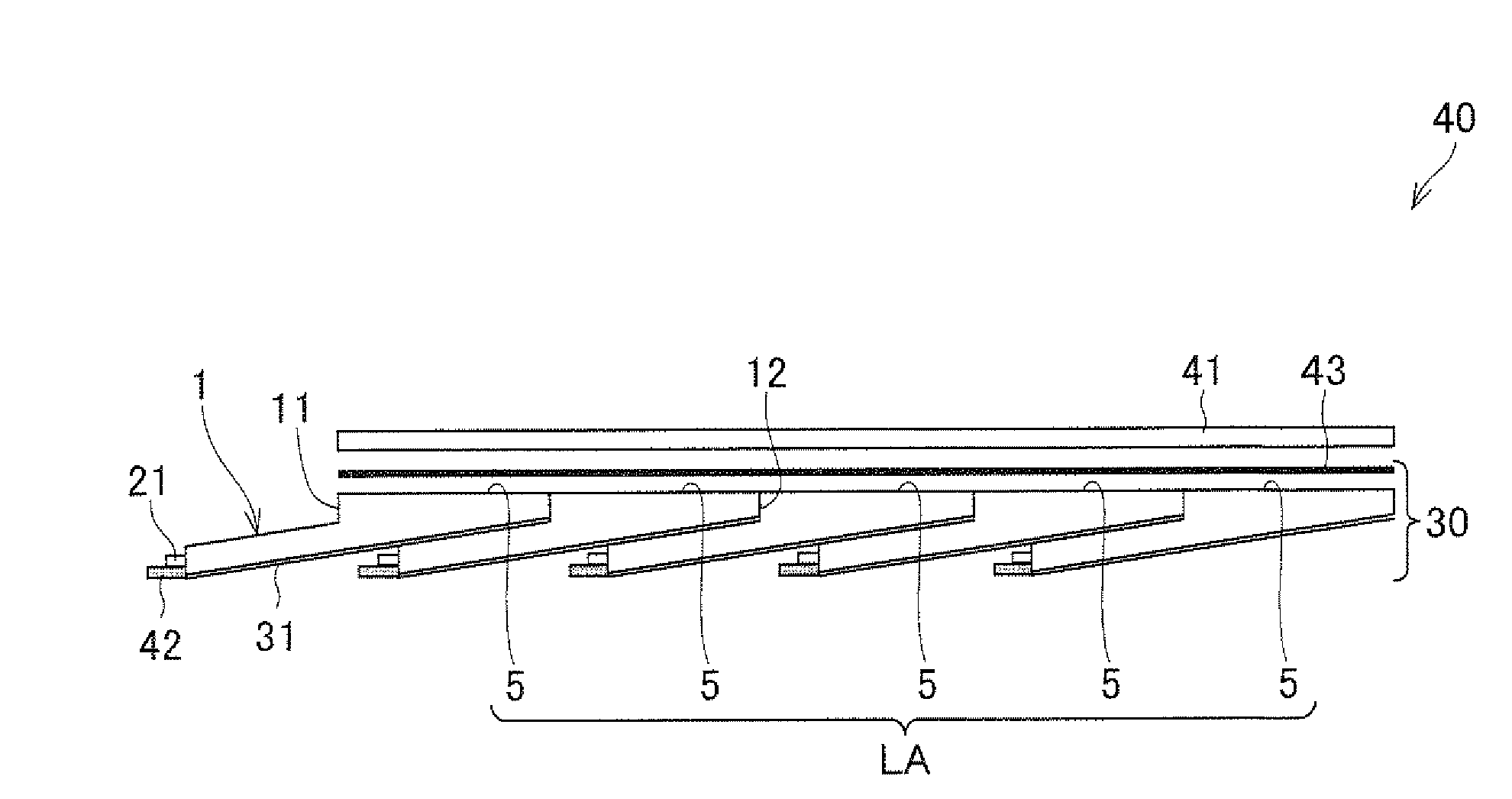
[0155]As shown in (a) of FIG. 1, a light source unit 20 in accordance with the present embodiment includes a light guide plate 1 (light guide body) and a plurality of light sources 21 (point light sources) provided on one end face of the light guide plate 1.

[0156]The light source unit 20 is a side-light light source unit (surface light source unit) that emits (surface radiation), from one principal surface (board face) thereof, light arriving at that end face of the light guide plate 1 on which the light sources 21 are provided.

[0157]The following describes each of the components. In the following description, for convenience o...

embodiment 2

[0288]The present embodiment is described below mainly with reference to (a) and (b) of FIG. 15. The present embodiment is described in terms of points of difference from Embodiment 1. Components having the same functions as those of Embodiment 1 are given the same reference numerals, and as such, will not be described below.

[0289]FIG. 15 shows (a) a plan view schematically showing the configuration of a light source unit 20 in accordance with the present embodiment and (b) a cross-sectional view of a light guide plate 1 of the light source unit 20 taken along the line D-D of (a) of FIG. 15.

[0290]In the light source unit 20 in accordance with the present embodiment, the light guide plate 1 is provided with groove sections 13 (grooves) that replaces the slit section 8 of (a) and (b) of FIG. 1 as dividers that restrict transmission of light. That is, the light guide plate 1 in accordance with the present embodiment is constructed such that the illumination region 4 is divided into a p...

embodiment 3

[0302]The present embodiment is described below mainly with reference to (a) and (b) of FIG. 16 and (a) and (b) of FIG. 17. The present embodiment is described in terms of points of difference from Embodiments 1 and 2. Components having the same functions as those of Embodiment 1 and 2 are given the same reference numerals, and as such, will not be described below.

[0303]FIG. 16 shows (a) a plan view schematically showing the configuration of a light source unit 20 in accordance with the present embodiment and (b) a cross-sectional view of a light guide plate 1 of the light source unit 20 taken along the line E-E of (a) of FIG. 16. FIG. 17 shows (a) a plan view schematically showing the configuration of another light source unit 20 in accordance with the present embodiment and (b) a cross-sectional view of a light guide plate 1 of the light source unit 20 taken along the line F-F of (a) of FIG. 17.

[0304]A light source unit 20 in accordance with the present embodiment uses dividers, m...


PUM

PropertyMeasurementUnit
thicknessaaaaaaaaaa
widthaaaaaaaaaa
thicknessaaaaaaaaaa

Abstract

An illumination device (30) includes a plurality of light source units (BLU) each having a light guide plate (1) and a plurality of light sources (21). The light guide plate (1) has an illumination region (4) through which incident beams of light from the light sources (21) are emitted outward and a light guide region (3) through which the incident beams of light from the light sources (21) are guided toward the illumination region (4), with the light guide region (3) and the illumination region (4) laid side-by-side. The illumination region (4) is divided into a plurality of light-emitting sections by slit sections (8), provided in such a way as to extend along directions of optical axes of the light sources (21), which restrict transmission of light. At least one of the light sources (21) is provided to each of the light-emitting sections in such a way as to be placed side-by-side along the light guide region (3). Light source units (20) adjacent to each other along the directions of the optical axes of the light sources (21) are disposed so that the illumination region (4) of one of the light source units (BLU) covers at least a part of the light guide region (3) of the other light source unit (BLU). This makes it possible to retain the strength of the illumination device as a combination of light guide blocks while reducing leakage of light into an adjacent area.

Description

TECHNICAL FIELD[0001]The present invention relates to a low-profile illumination device capable of area-active drive, a display device using the illumination device, and a light guide plate for use in the illumination device.BACKGROUND ART[0002]In recent years, liquid crystal display devices, which have spread rapidly to take the place of cathode-ray tubes (CRTs), have been widely used in liquid crystal televisions, monitors, mobile phones, and the like thanks to their energy-saving, low-profile, lightweight features, etc. An example of a method for further exploiting these features is to improve an illumination device (so-called backlights) that is disposed in the back of a liquid crystal display device.[0003]Illumination devices are classified broadly into side-light backlights (referred to also as “edge-light backlights”) and direct backlights. A side-light backlight is configured to have a light guide plate provided behind a liquid crystal display panel and a light source provid...

Claims


Application Information

Patent Timeline
Patent Type & Authority Applications(United States)
IPC IPC(8): G06F3/038G02F1/13357F21S8/00
CPCG02B6/0028G02B6/0043G02B6/008G02B6/0068G02B6/0055
Inventor UENO, TETSUYAMASUDA, TAKESHIAJICHI, YUHSAKU
Owner SHARP KK
Why Eureka
Try Eureka