X-ray ct apparatus

a ct apparatus and x-ray technology, applied in the field of x-ray ct apparatuses, can solve the problems of difficult to obtain the appropriate actual control of x-ray tube current, and x-ray tube current modulation pattern, etc., to achieve suppress the exposure dose and improve the effect of image quality

Inactive Publication Date: 2010-10-07
HITACHI LTD +1
View PDF4 Cites 13 Cited by
  • Summary
  • Abstract
  • Description
  • Claims
  • Application Information

AI Technical Summary

Benefits of technology

[0028]In accordance with the present invention, it is possible to provide the X-ray CT apparatus capable of improving image quality as well as suppressing exposure dose by corresponding to variation of an X-ray absorption coefficient over time in a contrast examination.
[0029]FIG. 1 is an external view showing the general

Problems solved by technology

However, the X-ray CT apparatus in [Patent Document 1] calculates the output of the X-ray after transmitting through the object during rotation of an X-ray tube, there is a problem that the actual control of the X-ray tube current follows the X-ray output prior to several view portions.
However, while the irradiation X-ray amounts are different when the X-ray tube voltages are different, calculation of X-ray tube current modulation pattern in accordance with the X-ray tube current has not been disclosed concretely in [Patent Document 1] nor in [Pa

Method used


Image

  • X-ray ct apparatus
  • X-ray ct apparatus
  • X-ray ct apparatus

Examples


Embodiment Construction

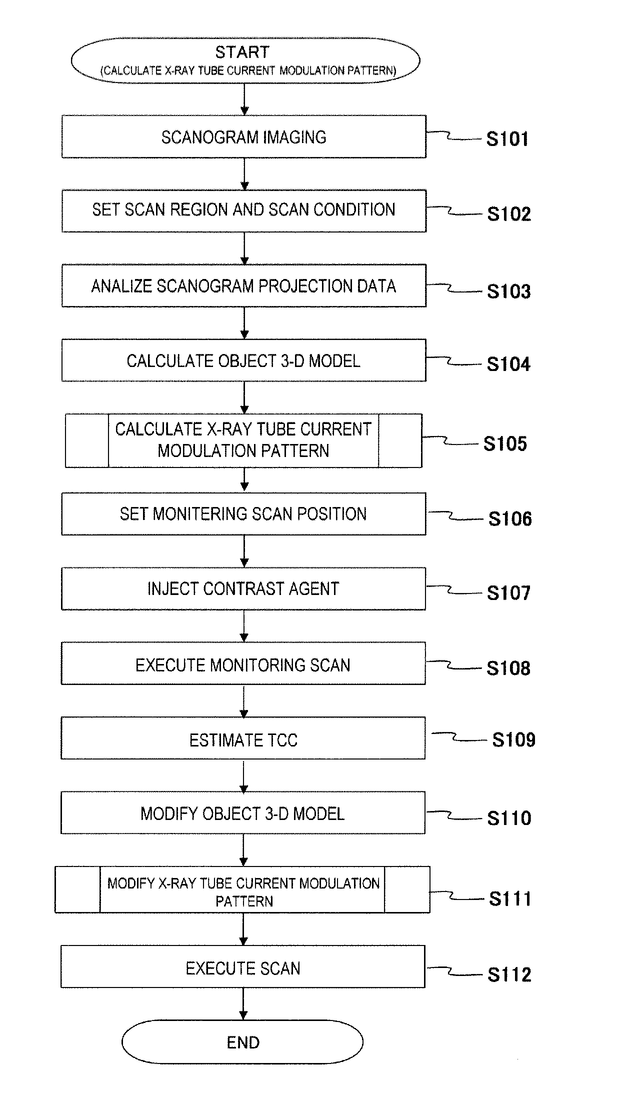
[0039]A preferred embodiment of the present invention will be described below referring to the attached diagrams. In the description and the attached diagrams below, the components having the same function will be appended with the same reference numerals and the repeated explanation will be omitted.

(1. Configuration of X-Ray CT Apparatus 1)

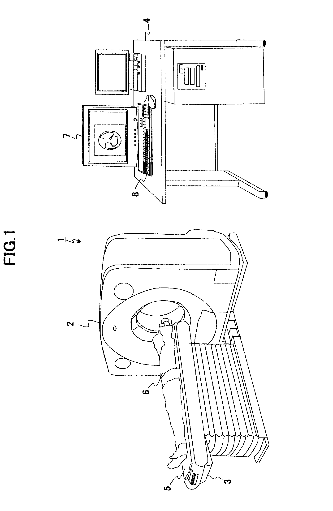
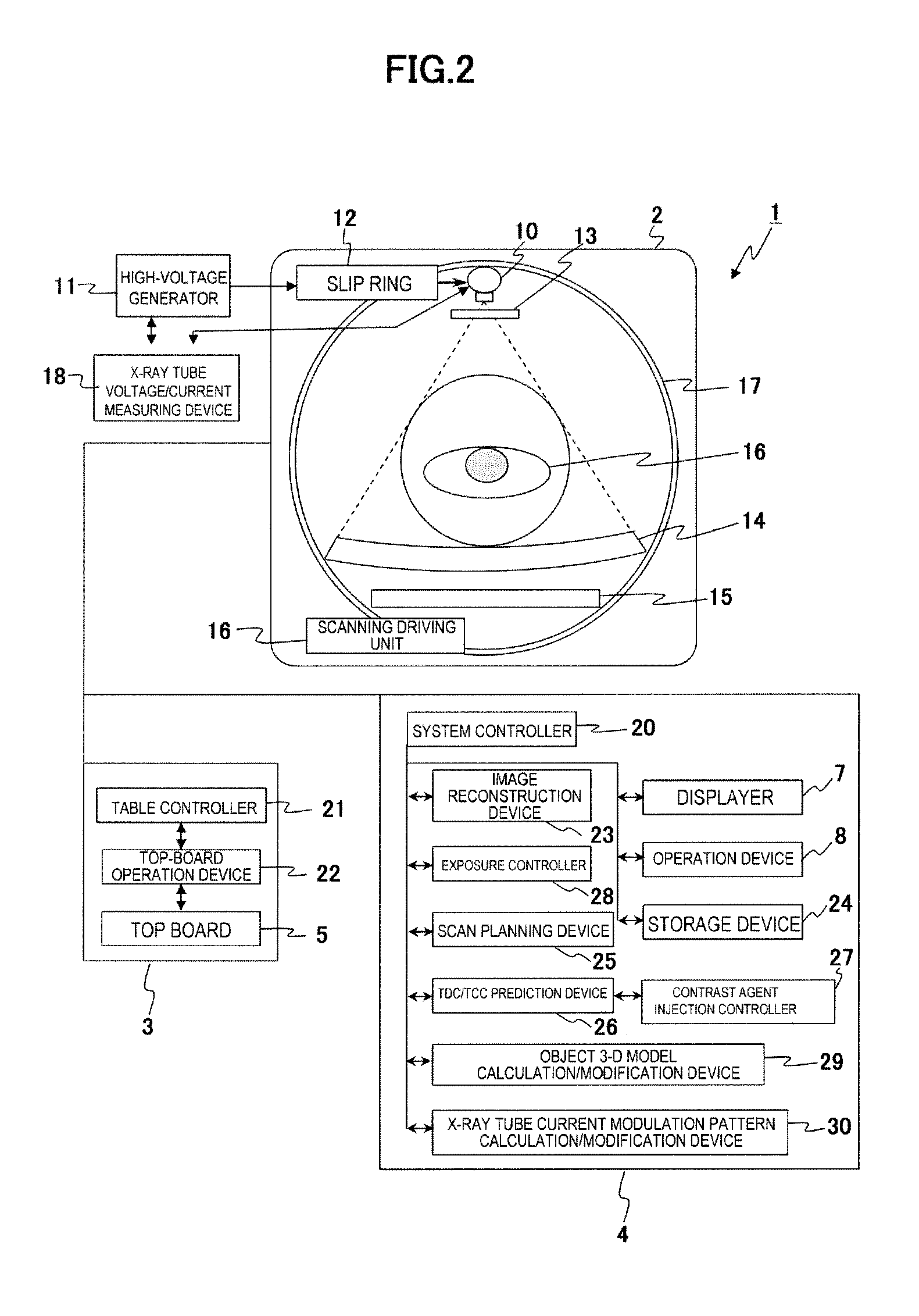
[0040]First, the configuration of X-ray CT apparatus 1 will be described referring to FIG. 1 and FIG. 2.

[0041]FIG. 1 is an external view of the general configuration of X-ray CT apparatus 1.

[0042]FIG. 2 is a block diagram of X-ray CT apparatus 1.

[0043]While the X-ray CT apparatus has one X-ray tube in the present embodiment, the present invention is also applicable to a multi-source type X-ray CT apparatus. Also, while there are various types of X-ray CT apparatuses such as the rotate-rotate method wherein an X-ray tube and an X-ray detector are integrated as one for irradiating wide fan beams to cover an object while rotating, the scanning elect...


PUM


Abstract

An X-ray CT apparatus is provided with an X-ray tube current modulation pattern calculation means that calculates an X-ray tube current modulation pattern based on a 3-dimensional model of an object calculated based on a scanogram image of the object, start-up shape acquisition means that acquires a start-up shape of CT values of a predetermined region of the object or CT value time differences after injecting contrast agent into the object, time contrast curve prediction means that predicts a time contrast curve indicative of a time sequential change of contrast in a diagnostic portion of the object at each slice position at a scan time based on the acquired start-up shape of the CT values or CT value time differences, object 3-dimensional model modification means that modifies a 3-dimensional model of the object based on the predicted time contrast curve, and X-ray tube electric current modulation pattern modification means that modifies the X-ray tube electric current modulation pattern based on the modified 3-dimensional model of the object.

Description

TECHNICAL FIELD[0001]The present invention relates to an X-ray CT apparatus, in particular to an X-ray CT apparatus which controls X-ray tube current during scan considering image quality and exposure dose.BACKGROUND ART[0002]An X-ray CT apparatus irradiates an X-ray of a fan beam or cone beam (conical shape or pyramid shape) to an object to be examined, acquires projection data which is the information related to intensity of the X-ray that is transmitted through the object, and scans distribution information of X-ray absorption coefficient in the object based on the acquired projection data.[0003]The X-ray CT apparatus acquires projection data in discrete X-ray tube positions (views). The view number per one rotation of an X-ray tube normally reaches from several hundreds to several thousands. The X-ray CT apparatus executes scanning by irradiating an X-ray while rotating an X-ray tube around the object, and acquires projection data of the view number necessary for reconstructing ...

Claims


Application Information

Patent Timeline
IPC IPC(8): A61B6/03
CPCA61B6/032A61B6/481H05G1/30A61B6/542A61B6/488G06T17/00
Inventor SUGAYA, YOSHIAKIGOTO, TAIGAHIROKAWA, KOICHIMIYAZAKI, OSAMU
Owner HITACHI LTD
Why Eureka
Try Eureka