

Mobile communication system and tunnel management method thereof
- Summary
- Abstract
- Description
- Claims
- Application Information
AI Technical Summary
Benefits of technology
Problems solved by technology
Method used
Image

Examples
Embodiment Construction
[0017]The advantages, features and aspects of the invention will become apparent from the following description of embodiments with reference to the accompanying drawings.
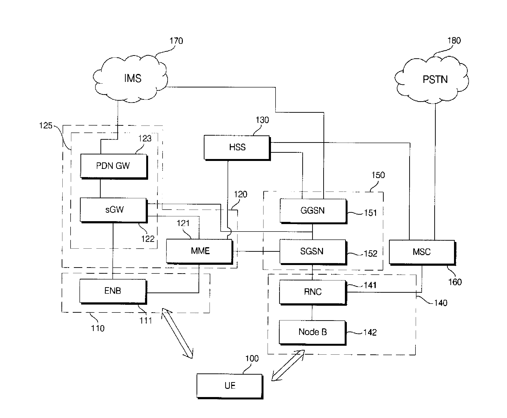
[0018]FIG. 1 is a diagram illustrating an evolved mobile communication network in accordance with an embodiment of the present invention.
[0019]Referring to FIG. 1, the evolved mobile communication network includes user equipment 100, an Evolved Universal Mobile Telecommunications Network Terrestrial Radio Access Network (E-UTRAN) 110, and an Evolved Packet Core (EPC) 120.
[0020]Such an evolved mobile communication network is connected to existing mobile communication networks and a Home Subscriber Server (HSS) 130 for registration, authentication, and verification of users so as to be connected to an IP Multimedia Subsystem (IMS) 170 and a Public Switched Telephone Network (PSTN) 180. The existing mobile communication network includes an UTRAN 140 having a Node B 142 and a Radio Network Controller (RNC) 141 for taki...
PUM
 Abstract
Description
Claims
Application Information