Apparatus for Displaying 3D Images

a technology of 3d images and apparatus, applied in the field of apparatuses that enable 3d displaying, can solve the problems of inability to display surfaces, confliction in viewer's 3d perception, vital drawbacks of transparency of volumetric displays, etc., and achieve the effect of increasing efficiency and brightness of displays

Inactive Publication Date: 2011-01-06
MICROVISION
View PDF20 Cites 48 Cited by
  • Summary
  • Abstract
  • Description
  • Claims
  • Application Information

AI Technical Summary

Benefits of technology

[0014]In all configurations, the scanning angle of the scanners can be limited to a specific narrow angle with a specific offset if only limited numbers of viewers are viewing the display from a limited viewing angle. This embodiment of the system is quiet advantageous as it will increase the efficiency and as a result brightness of the display.

Problems solved by technology

However, there is a vital inadequacy with today's 2D displays.
First group, holographic displays in spite of their great potential stemming from their 3D reconstruction quality, are not strong candidates for being widespread and commercial in the following years, due to high bandwidth requirements, demand for SLMs with high resolution and difficulties in achieving natural shading.
Second group, volumetric displays have a variety of approaches e.g. real image methods applying static or moving displays and few commercial products realizing these approaches.
The volumetric displays have the vital drawback of transparency.
It means that objects that should be behind some other objects, are not occluded by the front object and seen by the viewer which cause a confliction in viewer's 3D perception.
Another drawback with volumetric displays is their incapability of displaying surfaces having non-Lambertian intensity distributions.
However, auto stereoscopic displays have also their own drawbacks including: generation of pseudoscopic viewing regions, decrease in resolution with increasing view number, discontinuities and jumps between adjacent views, eye fatigue stemming from accordance problem of accommodation and vergence mechanisms of the eye.

Method used


Image

  • Apparatus for Displaying 3D Images
  • Apparatus for Displaying 3D Images
  • Apparatus for Displaying 3D Images

Examples


Embodiment Construction

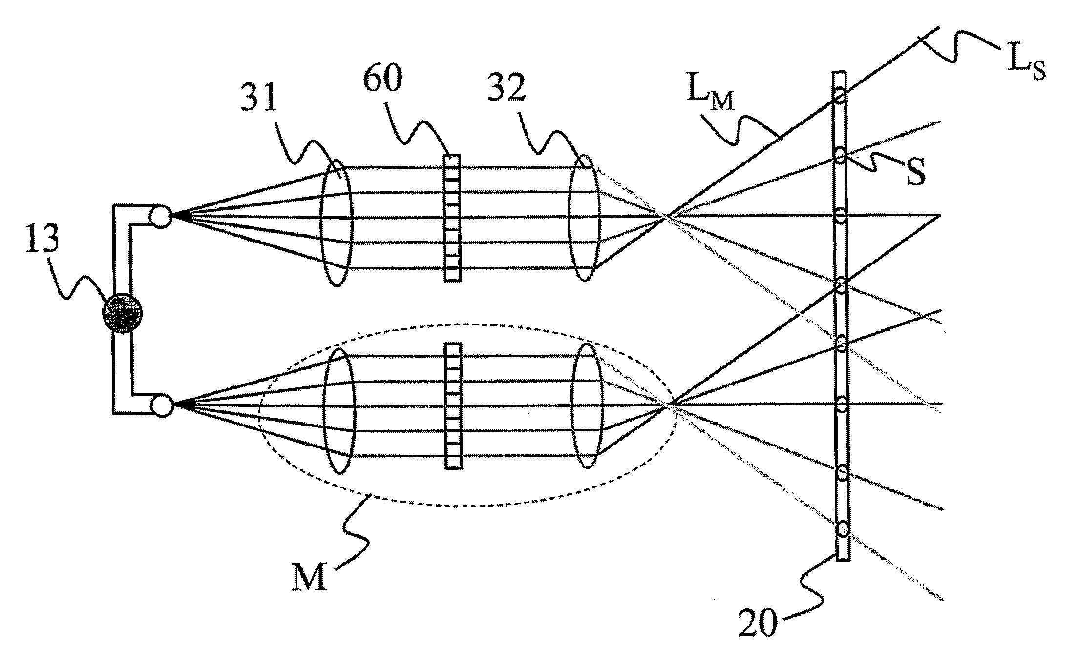
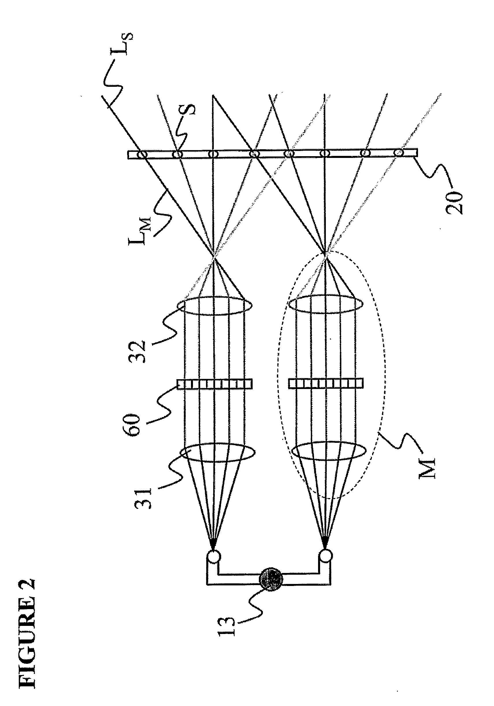
[0034]The light source 13, collimator 31, 2D micro display panels 60, and the lens system 32 in front of the micro display 60 in FIG. 2 mentioned above are replaced with a one-dimensional (1D) scanning module 101D coupled with at least one light source 13 per each color and an imaging lens 30 in front. In a preferred embodiment, 1D LED array per color (13R, 13G and 13B) is integrated onto the 1D scanning module 101D as the light source 13 of the system. A one-dimensional (1D) LED array per color 13 and the LED driver IC 14 integrated on a 1D scanning module 101D can be seen in FIG. 4(a), which constitutes the basic functional unit of the display system. In a preferred embodiment, the scanner 101D is made on FR4 substrate, a fiber-glass epoxy composite, using standard PCB technology [7] and scans in torsional mode via the flexible members 11 of the 1D scanning module 101D that are connected to a fixed platform 12. Depending on the number of LEDs per 1D scanning module 101D, the drive...


PUM


Abstract

A 3D visualization apparatus is described based on the method of generating different horizontal light emitting directions from different screen positions. This is achieved by way of an array of scanning light source modules placed behind the screen. The scanning modules can be implemented by using an array of ID or 2D scanning modules where each one is coupled with at least one light source.

Description

TECHNICAL FIELD[0001]The present invention relates generally to an apparatus that enables 3D displaying.BACKGROUND OF THE INVENTION[0002]Today's developed displays with advanced technologies including “Liquid Crystal Display (LCD)” show images with very high quality. However, there is a vital inadequacy with today's 2D displays. This inadequacy is a result of expressing the 3D real world on a 2D plane and ignoring the fact that human beings experience the real world through two different eyes. In vision of the real world, two eyes correspond to two different views for the visual system while traditional displays provide only one view to the visual system—the same view towards each eye. 3D Displays seem to be the next step in the evolution of displays and will overcome this inadequacy by providing different views to different eyes. With the incredible developments in the digital video processing and visualizing technologies, first commercial 3D display products are already available ...

Claims


Application Information

Patent Timeline
Patent Type & Authority Applications(United States)
IPC IPC(8): H04N13/04
CPCG02B27/225G02B27/2264H04N13/0493H04N13/0418H04N13/0404
Inventor UREY, HAKANSAYINTA, MURAT
Owner MICROVISION
Why Eureka
Try Eureka