Microfluidic device

a microfluidic device and cytometry technology, applied in the field of microfluidic cytometry systems, can solve the problems of limiting the sterility and operator protection of the system, the droplet cell sorter is not particularly biosafe, and the type of system does not lend itself to the sterility and operator protection required, so as to achieve the effect of simulating regions

Inactive Publication Date: 2011-01-06
SONY CORP +1
View PDF30 Cites 70 Cited by
  • Summary
  • Abstract
  • Description
  • Claims
  • Application Information

AI Technical Summary

Problems solved by technology

Droplet cell sorters, however, are not particularly biosafe.
Unfortunately, this type of system does not lend itself to the sterility and operator protection required for routine sorting of patient samples in a clinical environment.
This longer cycle time limits fluid switching cell sorters to processing rates of several hundred cells per second.

Method used


Image

  • Microfluidic device
  • Microfluidic device
  • Microfluidic device

Examples


Embodiment Construction

[0047]For the purposes of promoting an understanding of the principles of the disclosure, reference will now be made to the embodiments illustrated in the drawings and specific language will be used to describe the same. It will nevertheless be understood that no limitation of the scope of the disclosure is thereby intended, such alterations and further modifications in the illustrated device, and such further applications of the principles of the disclosure as illustrated therein are contemplated as would normally occur to one skilled in the art to which the disclosure relates.

Microfluidic Device Having Data Storage Capacity

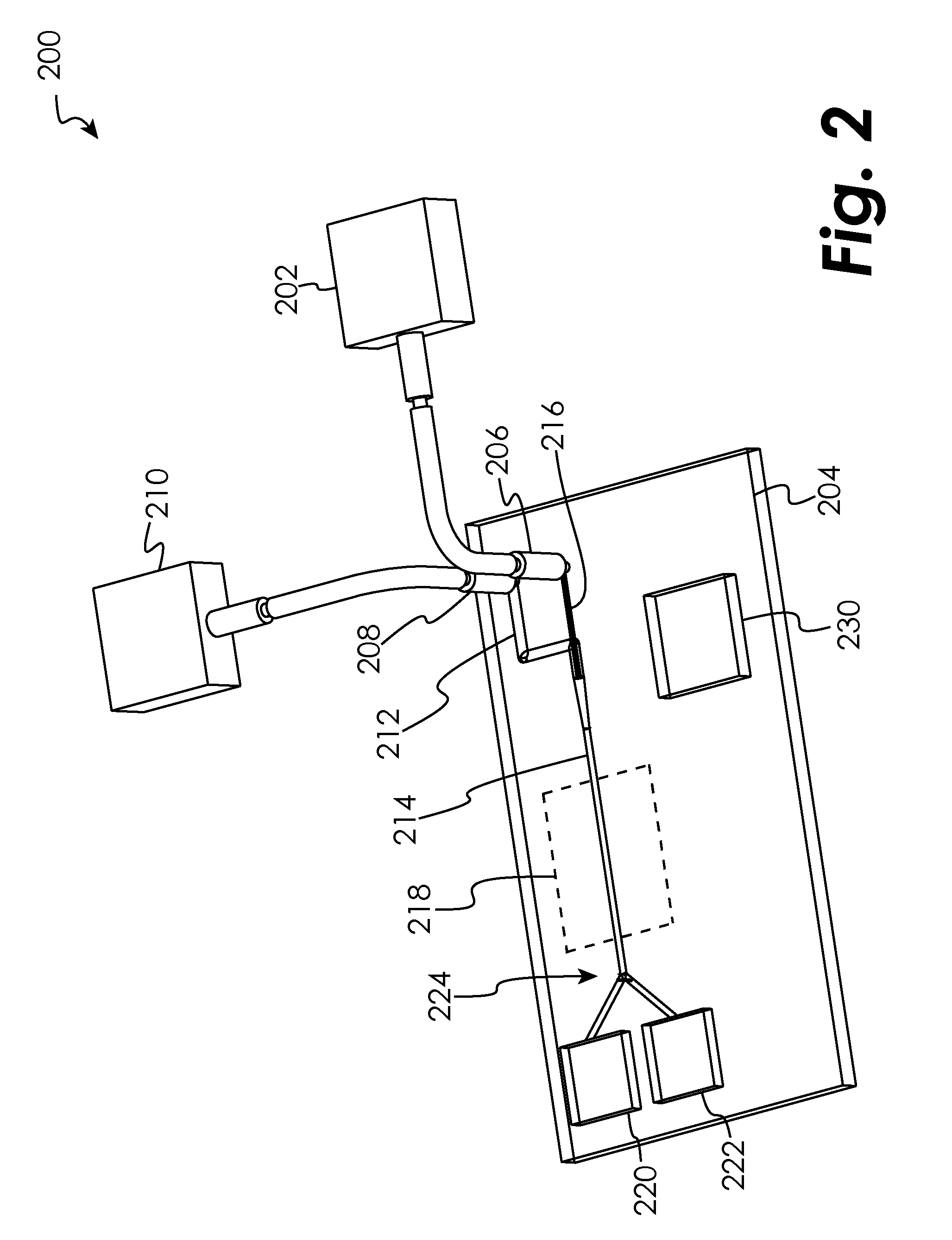
[0048]Certain embodiments of the present disclosure are generally directed to a system for the storage and retrieval of data on a microfluidic cytometry device, such as a cytometry chip. In FIG. 2, a system 200 is schematically illustrated in which cells coming from an external cell supply 202 are analyzed via cytometry using a microfluidic device formed onboard...


PUM

PropertyMeasurementUnit
concentrationaaaaaaaaaa
thermal conductivityaaaaaaaaaa
fluorescentaaaaaaaaaa

Abstract

The present disclosure relates to microfluidic devices adapted for facilitating cytometry analysis of particles flowing therethrough. In certain embodiments, the microfluidic devices have onboard data storage capabilities. In certain other embodiments, the microfluidic devices have onboard anticoagulants. In certain other embodiments, the microfluidic devices have onboard test and control channels. In certain other embodiments, the microfluidic devices have integrated collection media. In certain other embodiments, the microfluidic devices have multiple onboard test channels. In certain other embodiments, the microfluidic devices have localized temperature control. In certain other embodiments, the microfluidic devices have anatomy simulating regions. In certain other embodiments, the microfluidic devices have complete assay capabilities. In certain other embodiments, the microfluidic devices have dissociable sections. In certain other embodiments, the microfluidic devices have means for performing functional assays.

Description

CROSS-REFERENCE TO RELATED APPLICATIONS[0001]The present application claims the benefit of the following: U.S. Provisional Patent Application No. 61 / 223,415, which was filed Jul. 7, 2009, U.S. Provisional Patent Application No. 61 / 223,411, which was filed Jul. 7, 2009, U.S. Provisional Patent Application No. 61 / 223,742, which was filed Jul. 8, 2009, U.S. Provisional Patent Application No. 61 / 223,081, which was filed Jul. 6, 2009, U.S. Provisional Patent Application No. 61 / 223,084, which was filed Jul. 6, 2009, U.S. Provisional Patent Application No. 61 / 223,086, which was filed Jul. 6, 2009, U.S. Provisional Patent Application No. 61 / 223,088, which was filed Jul. 6, 2009, U.S. Provisional Patent Application No. 61 / 223,085, which was filed Jul. 6, 2009, U.S. Provisional Patent Application No. 61 / 223,405, which was filed Jul. 7, 2009, U.S. Provisional Patent Application No. 61 / 223,423, which was filed Jul. 7, 2009, U.S. Provisional Patent Application No. 61 / 223,425, which was filed Jul...

Claims


Application Information

Patent Timeline
Patent Type & Authority Applications(United States)
IPC IPC(8): C12M1/34C12Q1/04
CPCB01L3/502761B01L2200/027B01L2300/0877G01N2015/149G01N15/1463G01N15/1484G01N15/1459
Inventor DURACK, GARY P.
Owner SONY CORP
Why Eureka
Try Eureka