Methods and apparatus for detecting and locating leakage of digital signals

a digital signal and leakage detection technology, applied in the field of detection of leakage signals and the location of leakage sources, can solve the problems of ineffective leakage detection techniques the leakage detection technique is limited in the case of hfc network transmitting only digital signals, and the leakage detection technique is not effective for qam tv signals or other digital tv signals. , to achieve the effect of detecting leakag

Active Publication Date: 2011-02-24
ARCOM DIGITAL
View PDF56 Cites 41 Cited by
  • Summary
  • Abstract
  • Description
  • Claims
  • Application Information

AI Technical Summary

Benefits of technology

[0018]It is a further object of the present invention to provide methods and apparatus for det

Problems solved by technology

The known methods have limitations in cases where the HFC network transmits only digital signals, such as digital TV signals, like quadrature amplitude modulation (QAM) signals (“all-digital system”).
Current leakage detection techniques are not effective on leaks from QAM TV signals or other digital TV signals, because the leakage signal looks like pure noise.
Using a QAM receiver and demodulator also does not

Method used


Image

  • Methods and apparatus for detecting and locating leakage of digital signals
  • Methods and apparatus for detecting and locating leakage of digital signals
  • Methods and apparatus for detecting and locating leakage of digital signals

Examples


Embodiment Construction

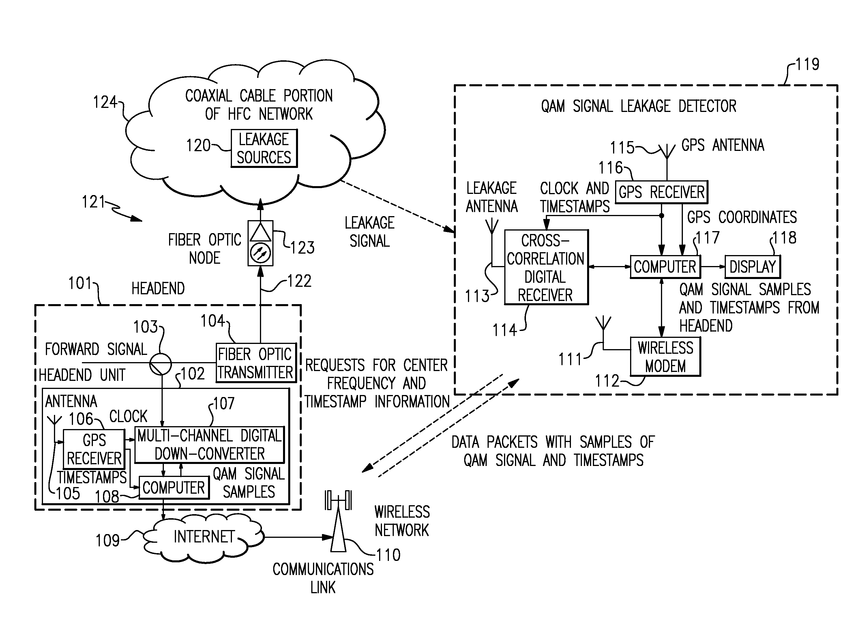
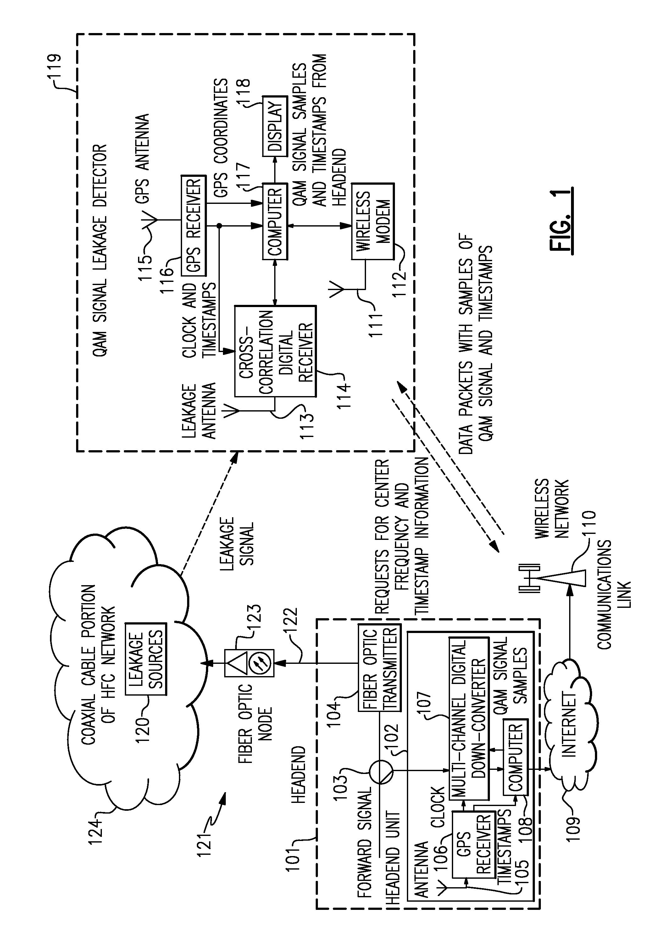
[0044]An exemplary embodiment of apparatus for detecting and locating a QAM leakage signal according to the present invention is illustrated in the schematic block diagram of FIG. 1. As an example, this embodiment is deployed in a cable television (or CATV) communications system, comprising a headend 101 and a hybrid fiber coax (HFC) network 121. HFC network 121 includes at least one fiber optic transmitter 104, a fiber optic cable portion 122, at least one fiber optic node 123, and a coaxial cable portion 124. HFC network 121 is a bi-directional communications network having a forward path (e.g., 54-1000 MHz) and a return path (e.g., 5-42 MHz), as is well-known and understood in the CATV industry. TV signals are transmitted from headend 101 to subscribers in the forward path and, generally, other types of communications between the subscribers and headend 101 occur in the return path. The design and construction of a bi-directional CATV HFC network are well-known and will not be fu...


PUM


Abstract

A system for detecting and locating a digital TV leakage signal in an HFC network. The system comprises a headend unit and a leakage detector. The headend unit receives the TV signal at the headend for use as a reference signal. The reference signal is sampled at a rate corresponding to a time reference signal, to produce reference signal samples. The reference signal samples and timestamp are transmitted to the leakage detector. The detector receives the digital TV signal from a leakage source, for detection as a leakage signal. The detector includes a cross-correlation processor. The leakage signal is sampled at a rate corresponding to the time reference signal, to produce leakage signal samples. The cross-correlation processor performs a cross-correlation of the reference signal samples with the leakage signal samples to produce a cross-correlation function having a peak, and the TV leakage signal is detected from this peak.

Description

BACKGROUND OF THE INVENTION[0001]1. Field of Invention[0002]The present invention relates generally to the detection of leakage signals and the location of leakage sources, and more particularly to methods and apparatus for detecting digital signals leaking from the coaxial cable portion of an HFC network and for locating the source or sources of the leaks.[0003]2. Background Art[0004]The tasks of detecting signals leaking from the coaxial cable portion of a hybrid fiber-coax (HFC) network and locating the source or sources of the leak are very important for controlling ingress and egress in an HFC network, such as an HFC cable television network.[0005]The known methods of leakage detection and location in HFC cable television networks can be divided into two groups. The first group involves the use of analog TV signals. The second group involves methods in which special pilot signals or carriers are inserted into the forward path spectrum and then these signals are used to detect l...

Claims


Application Information

Patent Timeline
IPC IPC(8): H04N17/00H04B17/40
CPCG01S5/06H04H20/12H04N17/004G01R31/08H04N21/4382H04N21/6118H04N21/2383
Inventor ZINEVICH, VICTOR M.
Owner ARCOM DIGITAL
Why Eureka
Try Eureka