Combined device for power generation and illumination mounted on the wheel axle of a bicycle

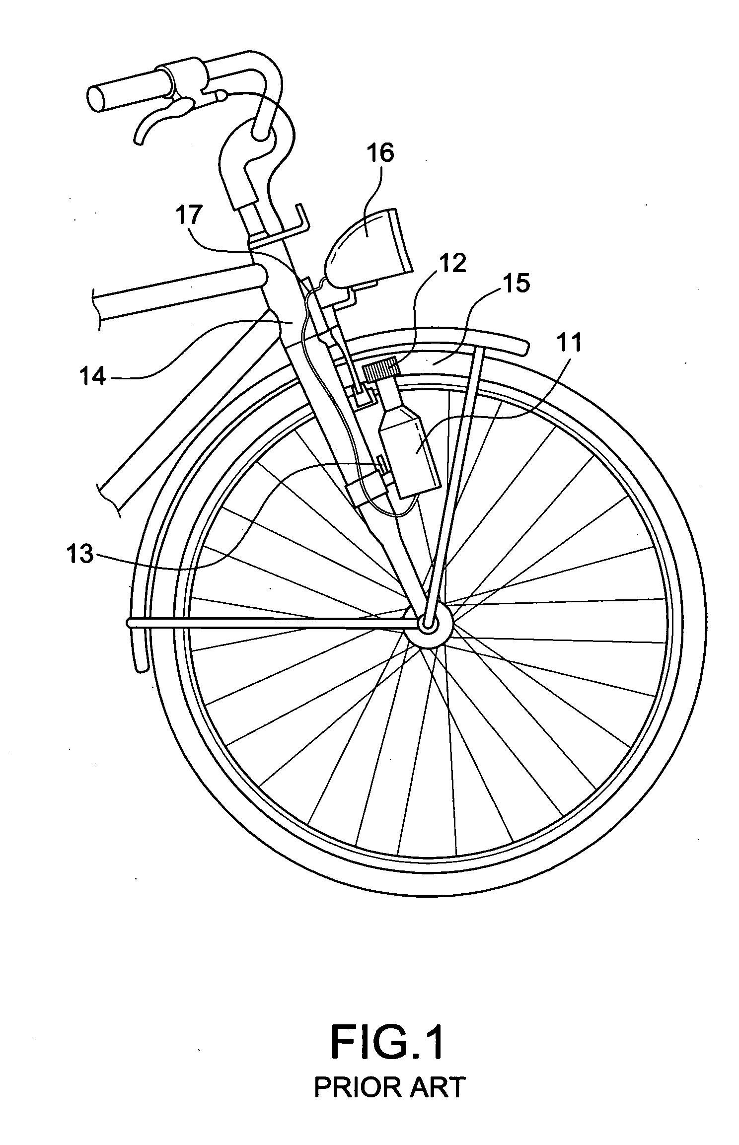
a technology of power generation and illumination, which is applied in the direction of bicycle equipment, lighting and heating equipment, optical signals, etc., can solve the problems of high failure rate, high rotation speed low efficiency of power generator b>11/b>, so as to improve structural integration and facilitate installation

Inactive Publication Date: 2011-05-19
LIN LILY
View PDF11 Cites 18 Cited by
  • Summary
  • Abstract
  • Description
  • Claims
  • Application Information

AI Technical Summary

Benefits of technology

[0017]A primary object of the present invention is to provide a combined device for power generation and illumination mounted on the wheel axle of a bicycle, and the combined device integrates the advantages of a dynamo power generation and a hub type power generation to overcome ...

Problems solved by technology

1. Low Efficiency: Since a single-phase power generator is adopted, the efficiency of the power generator 11 is very low, and the power generator 11 definitely requires a very high rotation speed to supply the electric power required for lighting up the bike lamp 16.
2. High failure rate: Since a high rotation speed is required, the driving wheel 12 is rotated at a very high rotation speed. However, the power generator 11 of that model does not come with a corresponding bearing for the high rotation speed, and thus incurs a high failure rate.
3. Large resistance: The power generator 11 of this model generate power by rubbing the power generator driving wheel 12 with a surface of the tire 15. To assure the contact between the power generator driving wheel 12 and the tire 15, the design of a stronger clutch 13 is provided for the tire 15 to drive the power generator 11 to rotate, so that the pressure of the power generator driving wheel 12 exerted upon the surface of the tire 15 is converted into a resistance, and bicycle rider can feel the large resistance and the hardship of riding the bike.
4. Exposure of electric wire: The bike lamp is not installed directly, and thus a segment of the electric wire 17 is exposed to connect the bike lamp 16, and the electric wire 17 may be pulled apart or deteriorated to cause a short circuit or a break of the electric wire.
1. Uneasy Installation: Since the power generator is installed onto the hub, a larger sized hub is required, unless the power generator is built in the wh...

Method used


Image

  • Combined device for power generation and illumination mounted on the wheel axle of a bicycle
  • Combined device for power generation and illumination mounted on the wheel axle of a bicycle
  • Combined device for power generation and illumination mounted on the wheel axle of a bicycle

Examples


Embodiment Construction

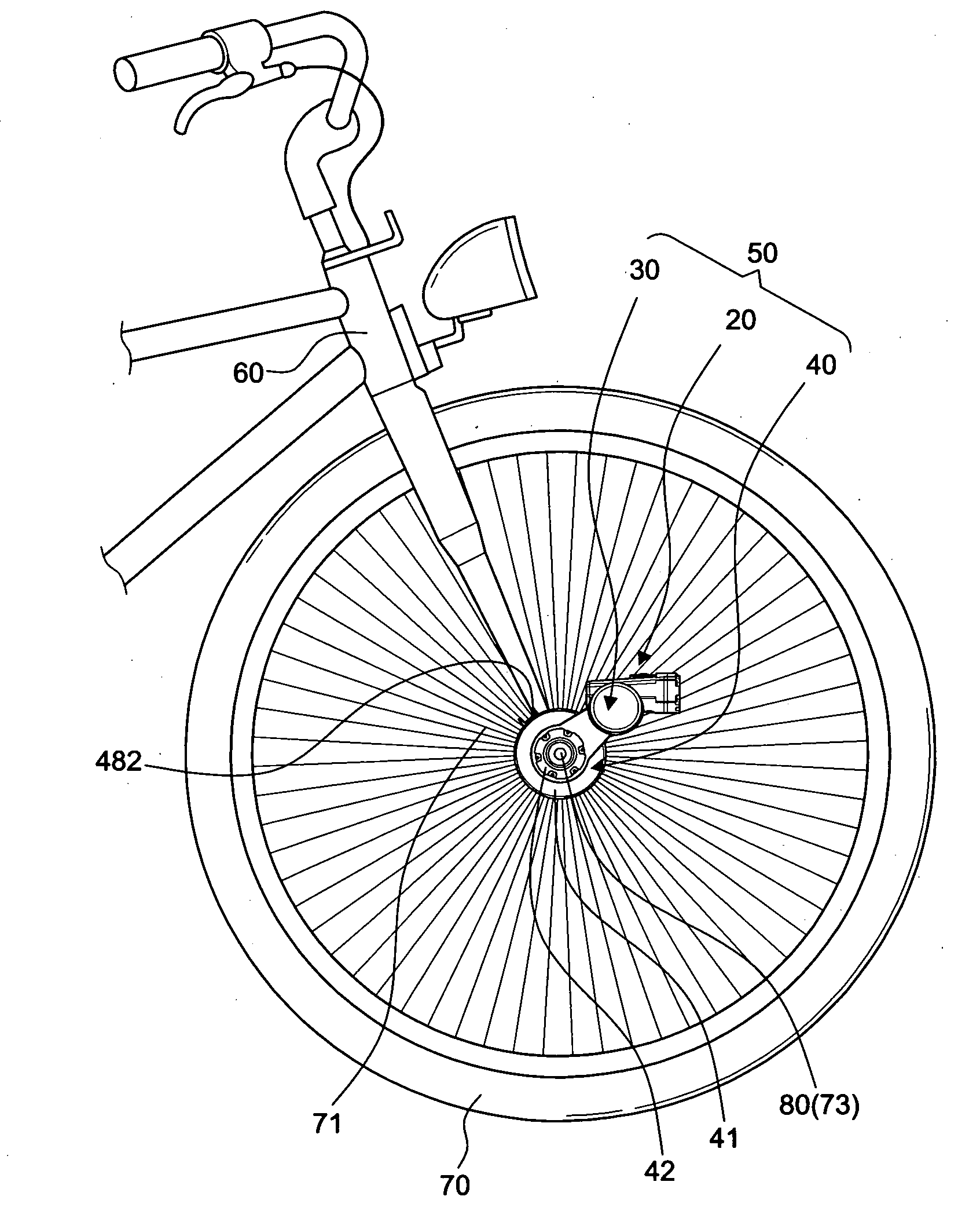
[0036]With reference to FIGS. 3 to 10 for a combined power generator and lamp device 50 of the present invention, the combined device 50 is formed by combining a head lamp 20, a power generator 30 coupled to the head lamp 20, and a transmission device 40 coupled to a wheel 70. The present invention is characterized in that the combined device 50 is hung and installed at an external portion of a wheel shaft 73 of the wheel 70. In other words, the combined device 50 will not ruin the original structure of the bicycle at all, and the combined device 50 can be detached quickly when it is not in use.

[0037]The head lamp 20 includes a lamp holder 21, a circuit board 23 installed in a containing space 22 of the lamp holder 21, a lamp 24 installed at a front side of the lamp holder 21 and electrically coupled to the circuit board 23, and a hollow installation base 29 disposed at the bottom of the lamp holder 21. In this preferred embodiment, the lamp 24 is secured onto an external side of th...


PUM


Abstract

A combined device for power generation and illumination mounted on the wheel axle of a bicycle, particularly a power generator of a bicycle combined with a lamp provides two or three other functions in addition to supplying a power source. The device is a standalone device hung on or installed at an external end of the bicycle wheel axle. Unlike a traditional way of rubbing with a tire, or a traditional hub type power generator, the combined power generation and light device has the features and advantages of an easily installation, a high efficiency, a low resistance, a low cost, a low failure rate, an integrated structure, a hidden electric wire and an adjustable angle.

Description

BACKGROUND OF THE INVENTION[0001]1. Field of the Invention[0002]The present invention relates to a combined device for power generation and illumination mounted on the wheel axle of a bicycle, and more particularly to a combined power generation and light device mounted onto an external side of a bicycle wheel axle, totally different from the traditional way of generating power by frictions produced between a hub and a tire of the bicycle.[0003]2. Description of the Related Art[0004]At present, there are various types of self power generation lamps used by bicycles and described as follows:[0005]The first type is generally known as dynamo powered lamps as shown in FIG. 1, wherein a small sized power generator 11 is installed at a fork 14 of a bicycle, and a clutch 13 is used for separating the power generator 11 from a tire 15 when the lamp is not in use, and attaching a driving wheel 12 of an axle of the power generator 11 with the tire 15 if light is needed, such that rotation of ...

Claims


Application Information

Patent Timeline
IPC IPC(8): B62J6/00
CPCB62J6/12B62J6/02B62J6/029B62J6/03
Inventor LIN, LILY
Owner LIN LILY
Why Eureka
Try Eureka