Endoscope apparatus

a technology of endoscope and endoscope, which is applied in the field of endoscope equipment, can solve the problems of difficult to aim the laser light for therapy at the lesion part, and achieve the effects of accurate laser light aiming, positive pdt, and high efficiency

Inactive Publication Date: 2011-05-19
FUJIFILM CORP
View PDF4 Cites 33 Cited by
  • Summary
  • Abstract
  • Description
  • Claims
  • Application Information

AI Technical Summary

Benefits of technology

[0009]With the endoscope apparatus, the laser light for diagnosis and the laser light for therapy can be arbitrarily switched therebetween and emitted from the endoscope leading end portion. Therefore, it is possible to perform the PDD and PDT smoothly and repeatedly. Further, it is possible to accurately aim the laser light for therapy at the object to be examined, so that it is possible to positively perform the PDT in high efficiency.

Problems solved by technology

Thereby, when the laser light for therapy is emitted toward the specified lesion part, it is difficult to aim the laser light for therapy at the lesion part and to continuously focus the laser light on the lesion part with accuracy because the PDT probe is movable independently of the endoscope leading end.

Method used


Image

  • Endoscope apparatus
  • Endoscope apparatus
  • Endoscope apparatus

Examples


Embodiment Construction

[0025]Hereinafter, illustrative embodiments of the invention will be described in detail with reference to the accompanying drawings.

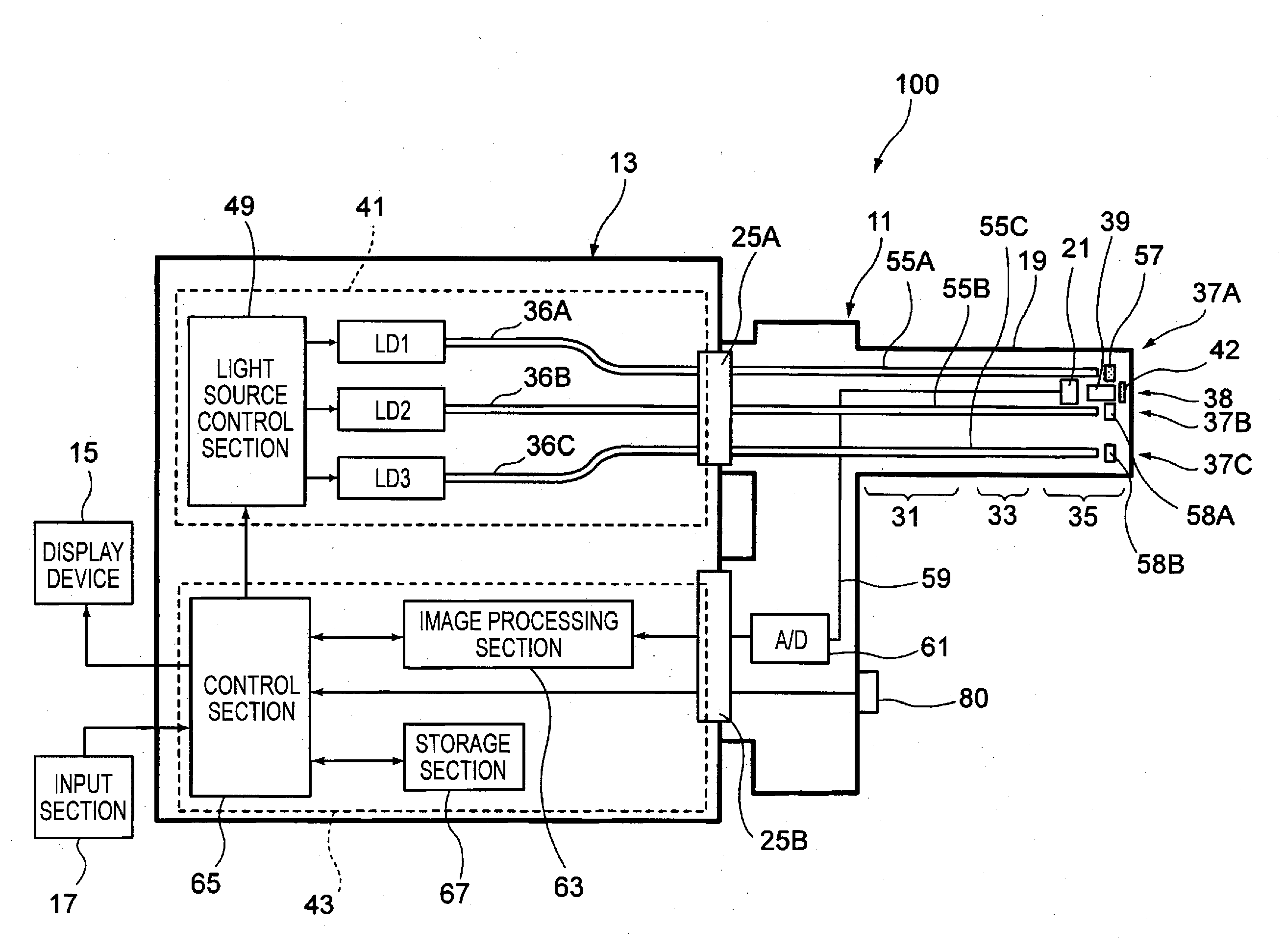
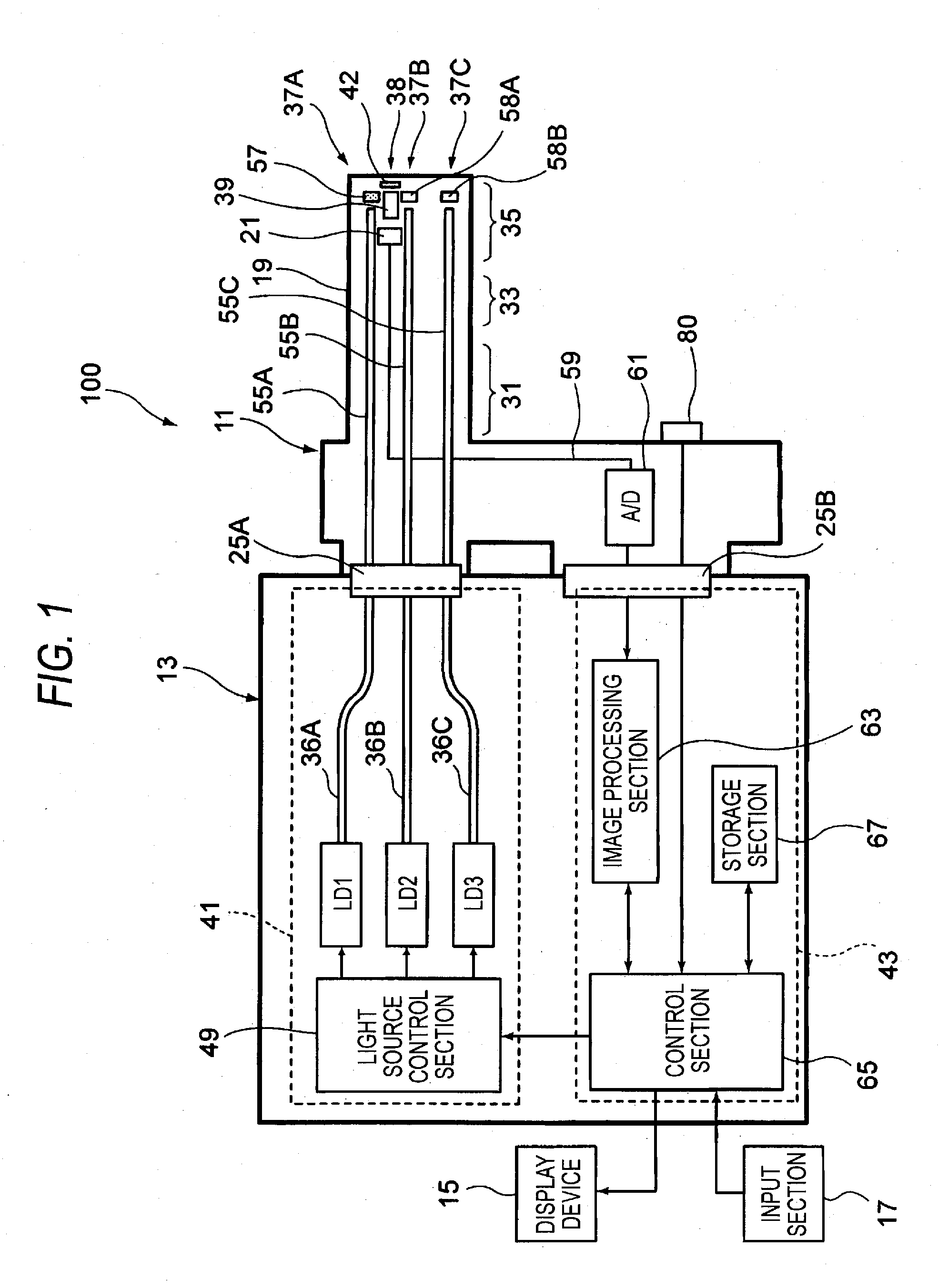
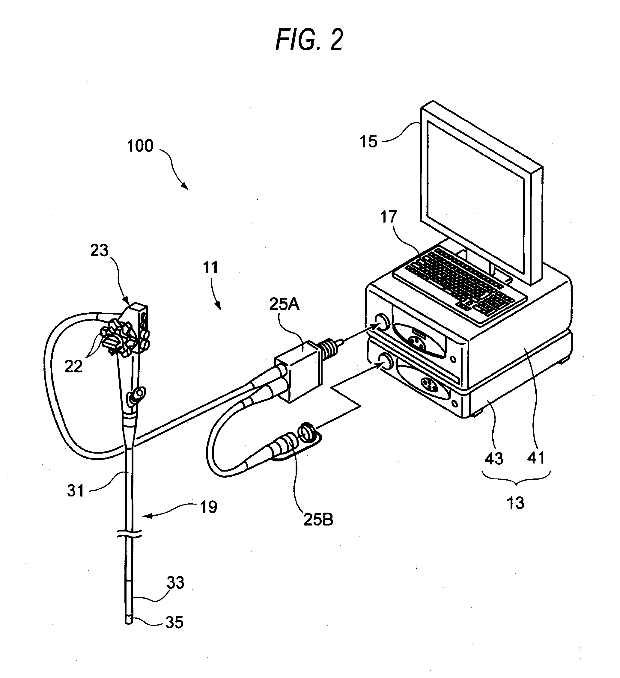
[0026]FIG. 1 is a conceptual block diagram of an endoscope apparatus according to one embodiment of the invention. FIG. 2 is an exemplary appearance view of the endoscope apparatus shown in FIG. 1.

[0027]As shown in FIGS. 1 and 2, an endoscope apparatus 100 has an endoscope 11 and a control device 13 that is connected to the endoscope 11. The control device 13 is connected to a display device 15 that displays image information and the like and an input section 17 that accepts an input operation. The endoscope 11 is an electronic endoscope having an illumination optical system that emits illumination light from a leading end of an endoscope insertion part 19, which is to be inserted into an object to be examined and an imaging optical system that includes an imaging device 21 (see FIG. 1) imaging an area to be observed.

[0028]Also, the endoscope 11 has th...


PUM


Abstract

An endoscope apparatus includes first and second light sources, an endoscope leading end portion, an irradiation window, an observation window, a light irradiation unit and an emission angle changing unit. The first light source outputs laser light for diagnosis. The second light source outputs laser light for therapy. The laser light for therapy is different in spectrum from the laser for diagnosis. The irradiation window and the observation window are provided in the endoscope leading end portion. The light irradiation unit emits the laser light for diagnosis and the laser light for therapy to the object through the irradiation window. The emission angle changing unit changes an emission angle at which the laser light for therapy is emitted through the irradiation window to be smaller than an emission angle at which the laser light for diagnosis is emitted. The object to be examined is observed through the observation window.

Description

CROSS-REFERENCE TO RELATED APPLICATIONS[0001]This application claims the benefit of Japanese Patent Application No. 2009-263912, filed Nov. 19, 2009, the entire contents of which are hereby incorporated by reference, the same as if set forth at length.BACKGROUND[0002]1. Technical Field[0003]The invention relates to an endoscope apparatus.[0004]2. Description of the Related Art[0005]Recently, technologies of photodynamic diagnosis (PDD) and photodynamic therapy (PDT) have been developed which emit laser light from a leading end of an insertion portion of an endoscope to diagnose and treat a tumor is developed in an interior wall of the body cavity. In the PDD and PDT, a photosensitive material having a tumor affinity property and being sensitive to specific excitation light is administered into the body in advance. In the PDD, laser light for diagnosis, which is excitation light, is applied to a body tissue surface to observe fluorescent light from a part where a concentration of the...

Claims


Application Information

Patent Timeline
Patent Type & Authority Applications(United States)
IPC IPC(8): A61B1/04
CPCA61B1/00188A61B1/045A61B1/0638A61B1/0669A61B1/07A61B2017/00057A61N5/0601A61N5/062A61N2005/063A61B1/043A61B1/063A61B1/0653A61B90/37A61N5/067A61B1/0655
Inventor ERIKAWA, AKIHIKO
Owner FUJIFILM CORP
Why Eureka
Try Eureka