Fan

a fan and fan body technology, applied in the direction of propulsive elements, propellers, containers, etc., can solve the problems of air flow, the cooling effect created by the fan diminishes with distance from the user, and the forward flow of air current produced by the rotating blades of the fan is not felt uniformly by the user, so as to reduce carbon debris and emissions, reduce the range of operating speeds, and reduce the effect of air flow generation

Active Publication Date: 2011-07-07
DYSON TECH LTD
View PDF99 Cites 112 Cited by
  • Summary
  • Abstract
  • Description
  • Claims
  • Application Information

AI Technical Summary

Benefits of technology

Advantageously, by this arrangement an air current is generated and a cooling effect is created without requiring a bladed fan. The bladeless arrangement leads to lower noise emissions due to the absence of the sound of a fan blade moving through the air, and a reduction in moving parts. The tapered diffuser portion enhances the amplification properties of the fan assembly while minimising noise and frictional losses over the surface. The arrangement and angle of the guide portion result in the shaping or profiling of the divergent air flow exiting the opening. Advantageously, the mean velocity increases as the air flow passes over the guide portion, which increases the cooling effect felt by a user. Advantageously, the arrangement of the guide portion and the diffuser portion directs the air flow towards a user's location while maintaining a smooth, even output without the user feeling a “choppy” flow. The invention provides a fan assembly delivering a suitable cooling effect that is directed and focussed as compared to the air flow produced by prior art fans.
The nozzle may be rotatable or pivotable relative to a base portion, or other portion, of the fan assembly. This enables the nozzle to be directed towards or away from a user as required. The fan assembly may be desk, floor, wall or ceiling mountable. This can increase the portion of a room over which the user experiences cooling.

Problems solved by technology

A disadvantage of this type of arrangement is that the forward flow of air current produced by the rotating blades of the fan is not felt uniformly by the user.
Uneven or “choppy” air flow can be felt as a series of pulses or blasts of air and can be noisy.
A further disadvantage is that the cooling effect created by the fan diminishes with distance from the user and the user may not be situated at the location or distance where it is possible to feel the greatest cooling effect.
For example, the base of a fan placed on, or close to, a desk reduces the area available for paperwork, a computer or other office equipment.
The shape and structure of a fan at a desk not only reduces the working area available to a user but can block natural light (or light from artificial sources) from reaching the desk area.
In addition, a well lit area can reduce eye strain and the related health problems that may result from prolonged periods working in reduced light levels.
In addition, it is undesirable for parts of the appliance to project outwardly, both for safety reasons and because such parts can be difficult to clean.

Method used


Image

  • Fan
  • Fan
  • Fan

Examples


Embodiment Construction

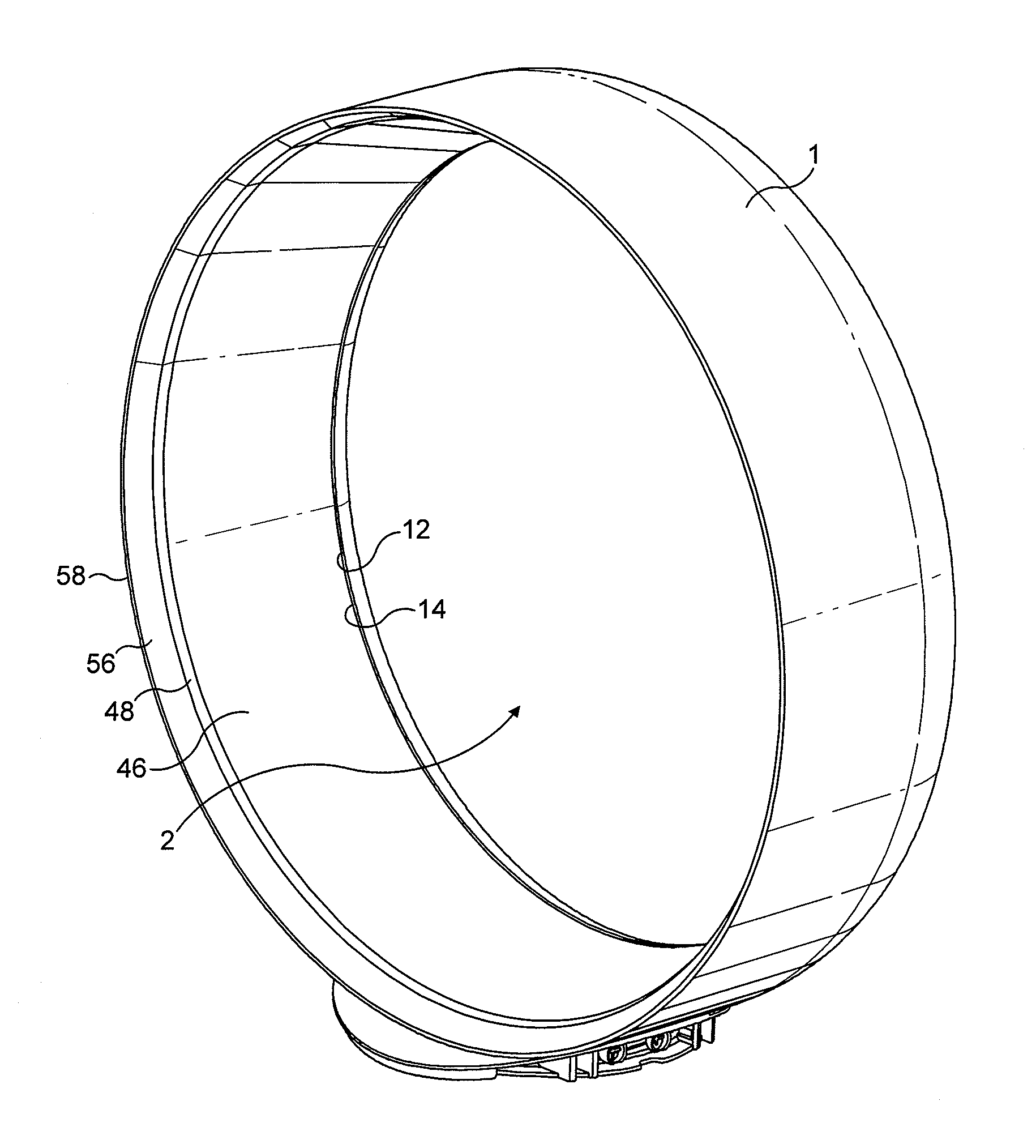
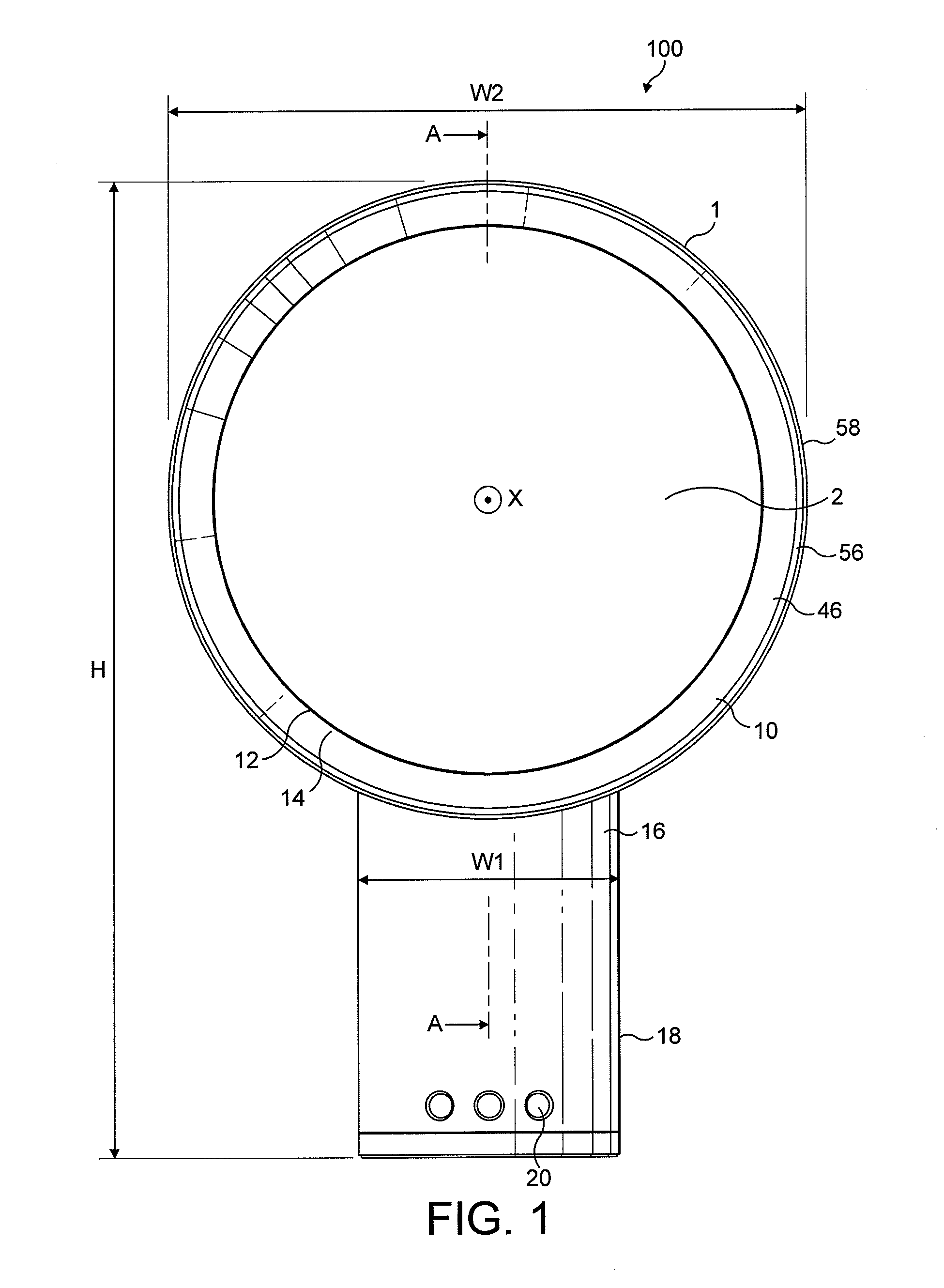
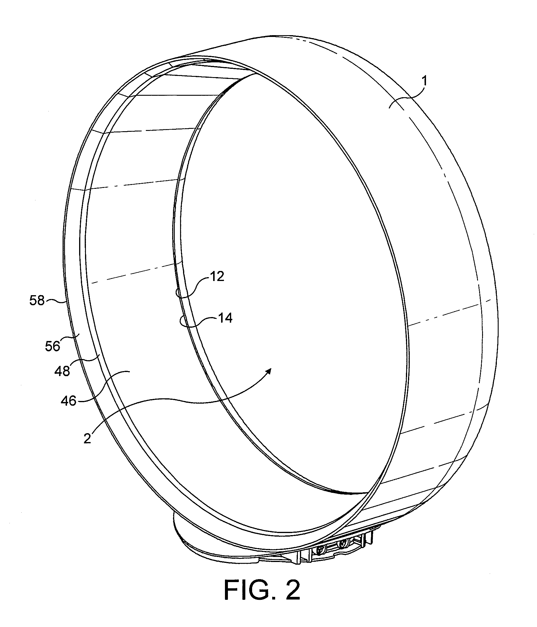
FIG. 1 illustrates an example of a fan assembly 100 viewed from the front of the device. The fan assembly 100 comprises an annular nozzle 1 defining a central opening 2. With reference also to FIGS. 2 and 3, the nozzle 1 comprises an interior passage 10, a mouth 12 and a Coanda surface 14 adjacent the mouth 12. The Coanda surface 14 is arranged so that a primary air flow exiting the mouth 12 and directed over the Coanda surface 14 is amplified by the Coanda effect. The nozzle 1 is connected to, and supported by, a base 16 having an outer casing 18. The base 16 includes a plurality of selection buttons 20 accessible through the outer casing 18 and through which the fan assembly 100 can be operated. The fan assembly has a height, H, width, W, and depth, D, shown on FIGS. 1 and 3. The nozzle 1 is arranged to extend substantially orthogonally about the axis X. The height of the fan assembly, H, is perpendicular to the axis X and extends from the end of the base 16 remote from the nozzle...


PUM


Abstract

A bladeless fan assembly for creating an air current includes a nozzle mounted on a base housing a device for creating an air flow through the nozzle. The nozzle includes an interior passage for receiving the air flow from the base and a mouth through which the air flow is emitted. The nozzle extends about an axis to define an opening through which air from outside the fan assembly is drawn by the air flow emitted from the mouth. The nozzle includes a surface over which the mouth is arranged to direct the air flow. The surface has a diffuser portion tapering away from the axis, and a guide portion downstream from the diffuser portion and angled thereto.

Description

FIELD OF THE INVENTIONThe present invention relates to a fan assembly. In its preferred embodiment, the present invention relates to a domestic fan, such as a desk fan, for creating air circulation and air current in a room, in an office or other domestic environment.BACKGROUND OF THE INVENTIONA conventional domestic fan typically includes a set of blades or vanes mounted for rotation about an axis, and drive apparatus for rotating the set of blades to generate an air flow. The movement and circulation of the air flow creates a ‘wind chill’ or breeze and, as a result, the user experiences a cooling effect as heat is dissipated through convection and evaporation. Such fans are available in a variety of sizes and shapes. For example, a ceiling fan can be at least 1 m in diameter, and is usually mounted in a suspended manner from the ceiling to provide a downward flow of air to cool a room. On the other hand, desk fans are often around 30 cm in diameter, and are usually free standing a...

Claims


Application Information

Patent Timeline
Patent Type & Authority Applications(United States)
IPC IPC(8): F03B5/00B05B1/00
CPCF04D25/08F04F5/16F04D33/00F04D29/441F04D29/545F04F5/20F04D29/40F04D29/44
Inventor FITTON, NICHOLAS GERALDNICOLAS, FREDERICGAMMACK, PETER DAVID
Owner DYSON TECH LTD
Why Eureka
Try Eureka