AI technical title is built by Patsnap AI team. It summarizes the technical point description of the patent document.
a cutting device and ultrasonic technology, applied in the field of ultrasonic cutting devices, can solve the problems of limiting the mobility of the operator, affecting the operation of the operator,
Active Publication Date: 2011-07-14
COVIDIEN AG
View PDF16 Cites 4 Cited by
Summary
Abstract
Description
Claims
Application Information
AI Technical Summary
This helps you quickly interpret patents by identifying the three key elements:
Problems solved by technology
Method used
Benefits of technology
Benefits of technology
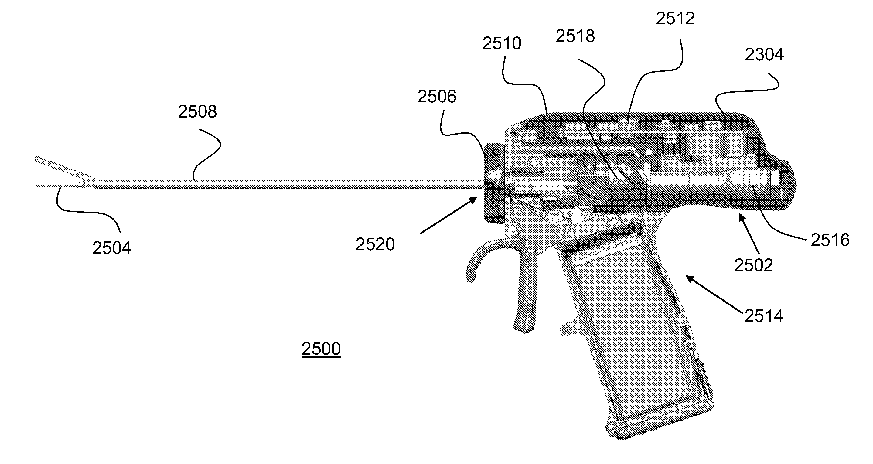
[0025]Briefly, in accordance with exemplary embodiments of the present invention, a cordless handheld apparatus that is capable of performing continuous ultrasonic cutting and cauterizing is disclosed. The invention includes a power supply, a control circuit, a drive circuit, and a matching circuit—all located within a handpiece of the ultrasonic cutting device and all operating and generating waveforms at battery voltages. Advantageously, the invention allows components to be replaced or moved between different devices.
[0026]The present invention, according to several embodiments, allows components of the device to be removed, replaced, serviced, and / or interchanged. Some components are “disposable,” which, as used herein, means that the component is used for only one procedure and is then discarded. Still other components are “reusable,” which, as used herein, means that the component can be aseptically cleaned and then used for at least a second time. As will be explained, other components are provided with intelligence that allows them to recognize the device to which they are attached and to alter their function or performance depending on several factors.
Problems solved by technology
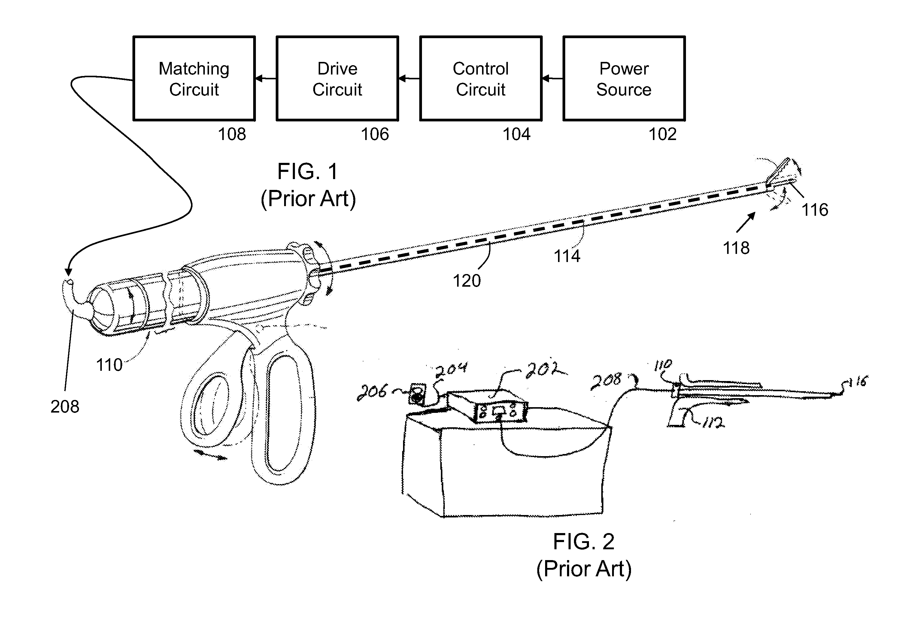
The prior art devices present a great disadvantage because the cord 208 has a length, size, and weight that restricts the mobility of the operator.
The cord 208 creates a tether for the operator and presents an obstacle for the operator and those around him / her during any surgical procedure using the handpiece 112.
In addition, the cord must be shielded and durable and is very expensive.
Another disadvantage exists in the prior art due to the frequency sensitivity of the matching circuit 108, the transducer 110, and the waveguide 114.
This architecture introduces transmission losses and electrical parasitics, which are common products of ultrasonic-frequency transmissions.
For this reason, maintaining constant current is not an effective way of maintaining a constant movement of the waveguide 114.
This precision brings with it a significant increase in cost.
These devices, however, do not currently appear in the marketplace and the written descriptions of each disclose virtually no details of how their circuitry is enabled.
However, in some surgeries, a cutting tool reaches its maximum lifespan within very few surgeries or, in some cases, even before the surgery is finished.
It was not designed or envisioned to use modern, long-lasting, high-power batteries, such as lithium-ion (Li) batteries.
Sakurai cannot provide this necessary feature because, by design, the sealed autoclavable Sakurai device does not and cannot have a plurality of external exposed contacts to be coupled to a charging device.
In fact, the inductive charging feature for the sealed device is entirely at odds with exposed contacts.
Method used
Image
Click on the blue label to locate the original text in one second.
Reading with bidirectional positioning of images and text.
Examples
Embodiment Construction
[0107]It is to be understood that the disclosed embodiments are merely exemplary of the invention, which can be embodied in various forms. Therefore, specific structural and functional details disclosed herein are not to be interpreted as limiting, but merely as a basis for the claims and as a representative basis for teaching one skilled in the art to variously employ the present invention in virtually any appropriately detailed structure. Further, the terms and phrases used herein are not intended to be limiting; but rather, to provide an understandable description of the invention.
[0108]Before the present invention is disclosed and described, it is to be understood that the terminology used herein is for the purpose of describing particular embodiments only and is not intended to be limiting. In this document, the terms “a” or “an”, as used herein, are defined as one or more than one. The term “plurality,” as used herein, is defined as two or more than two. The term “another,” as...
PUM
Property
Measurement
Unit
voltage
aaaaa
aaaaa
ultrasonic frequency
aaaaa
aaaaa
voltage
aaaaa
aaaaa
Abstract
An ultrasonic surgical assembly includes an ultrasonic-movement-generator assembly having a shell and an ultrasonic-driving-wave-signal generating circuit housed within the shell, an ultrasonic transducer having a proximal end and an ultrasonic-movement-producing distal end, an ultrasonic waveguide having a proximal end for receiving ultrasonic movement thereat, and a handle body having a waveguide attachment dock operable to accept the waveguide therein, an ultrasonic-movement-generator assembly dock operable to selectively removably secure the ultrasonic-movement-generator assembly thereto, and a transducer attachment dock operable to substantially simultaneously selectively removably and rotatably freely couple the ultrasonic transducer to the handle body rotationally independent of the ultrasonic-movement-generator assembly and axially align the ultrasonic-movement-producing distal end opposite the proximal end of the ultrasonic waveguide when the ultrasonic waveguide is disposed within the waveguide attachment dock.
Description
CROSS-REFERENCE TO RELATED APPLICATIONS[0001]This application is:[0002]a continuation-in-part of U.S. patent application Ser. Nos. 12 / 266,101 filed on Nov. 6, 2008; 12 / 266,146 filed on Nov. 6, 2008; 12 / 266,226 filed on Nov. 6, 2008; 12 / 266,252 filed on Nov. 6, 2008; 12 / 266,320 filed on Nov. 6, 2008; 12 / 266,664 filed on Nov. 7, 2008; 12 / 269,544 filed on Nov. 12, 2008; 12 / 269,629 filed on Nov. 12, 2008; and 12 / 270,146 filed on Nov. 13, 2008 (which applications each claim priority to U.S. Provisional Application Ser. Nos. 60 / 991,829 filed on Dec. 3, 2007; 60 / 992,498 filed on Dec. 5, 2007; 61 / 019,888 filed on Jan. 9, 2008; 61 / 045,475 filed on Apr. 16, 2008; 61 / 048,809 filed on Apr. 29, 2008; and 61 / 081,885 filed on Jul. 18, 2008);[0003]is a divisional of U.S. patent application Ser. Nos. 12 / 547,898, 12 / 547,975, and 12 / 547,999, all filed on Aug. 26, 2009; and[0004]is a divisional of U.S. Patent Application Attorney Docket “GATS Assem 1-pc”, filed concurrently herewith;[0005]is a division...
Claims
Application Information
Patent Timeline
Application Date:The date an application was filed.
Publication Date:The date a patent or application was officially published.
First Publication Date:The earliest publication date of a patent with the same application number.
Issue Date:Publication date of the patent grant document.
PCT Entry Date:The Entry date of PCT National Phase.
Estimated Expiry Date:The statutory expiry date of a patent right according to the Patent Law, and it is the longest term of protection that the patent right can achieve without the termination of the patent right due to other reasons(Term extension factor has been taken into account ).
Invalid Date:Actual expiry date is based on effective date or publication date of legal transaction data of invalid patent.
Patent Type & AuthorityApplications(United States)

