Medical equipment and endoscope apparatus

a technology of endoscope and endoscope, which is applied in the field of medical equipment and endoscope equipment, can solve the problems of damage or deviation of optical axes, difficult to stably match the optical axes of all optical fibers with high precision all the time, and achieve low loss optical connection, stable guide laser light all the time, and simple operation

Inactive Publication Date: 2011-07-28
FUJIFILM CORP
View PDF10 Cites 44 Cited by
  • Summary
  • Abstract
  • Description
  • Claims
  • Application Information

AI Technical Summary

Benefits of technology

[0008]The invention has been made in view of the above circumstances, and may provide a medical equipment capable of precisely connecting optical fibers with a simple operation and realizing optical connection with low loss and may stably guide laser light all the time.
[0009]With the above medical equipment and endoscope apparatus, when the optical connector is connected, the plurality of engagement pairs having different engagement beginning positions are sequentially engaged, so that it is possible to increase the positioning precision step by step. When the connection of the optical connector is completed, optical axes of the optical fibers are automatically matched with high precision. Therefore, it is possible to simply connect the optical fibers with low loss, so that it is possible to stably guide laser light.

Problems solved by technology

However, in order to collectively connect the plurality of pairs of plug-side holder and the receptacle-side holder, it is necessary to highly precisely assemble the plug-side and the receptacle-side, which causes difficulty in manufacturing and / or handling.
Also, a simple plug connection operation of just inserting the plug into the receptacle may cause damage or deviation of an optical axis due to shock in connecting the plug and the receptacle, depending on the insertion operation of the plug.
Thus, it is, in general, difficult to stably match the optical axes of all optical fibers with high precision all the time.

Method used


Image

  • Medical equipment and endoscope apparatus
  • Medical equipment and endoscope apparatus
  • Medical equipment and endoscope apparatus

Examples


Embodiment Construction

[0037]Hereinafter, embodiments of the invention will be described with reference to the accompanying drawings.

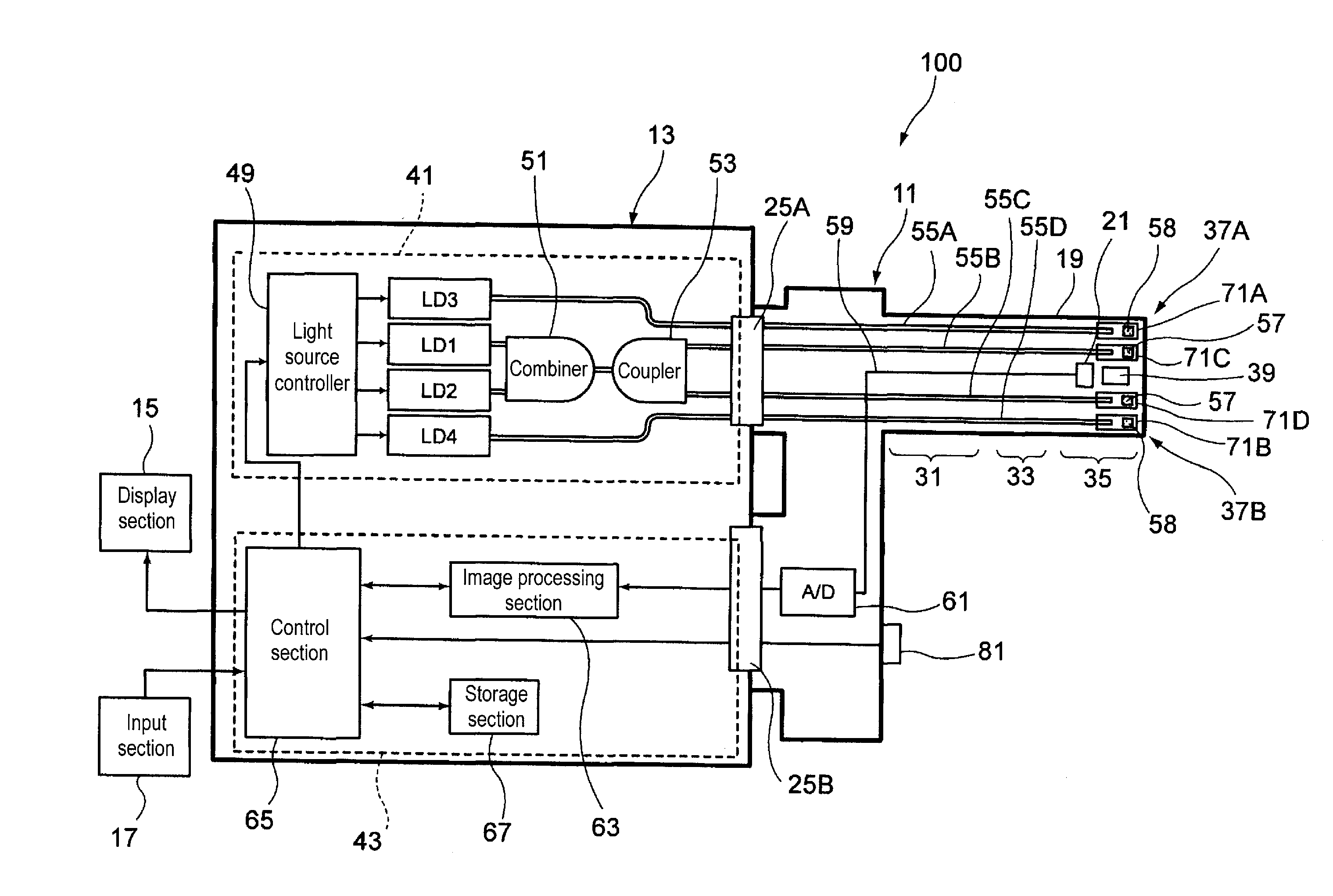
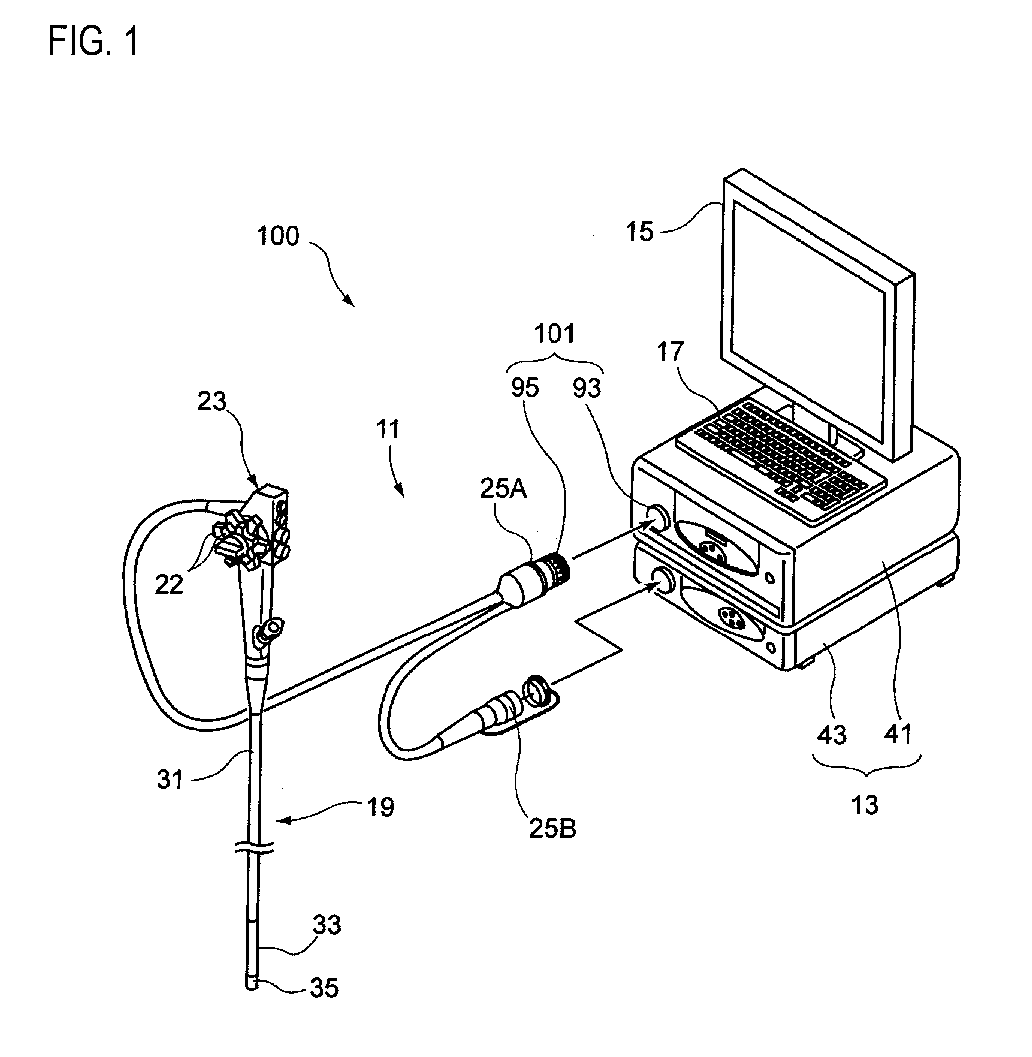
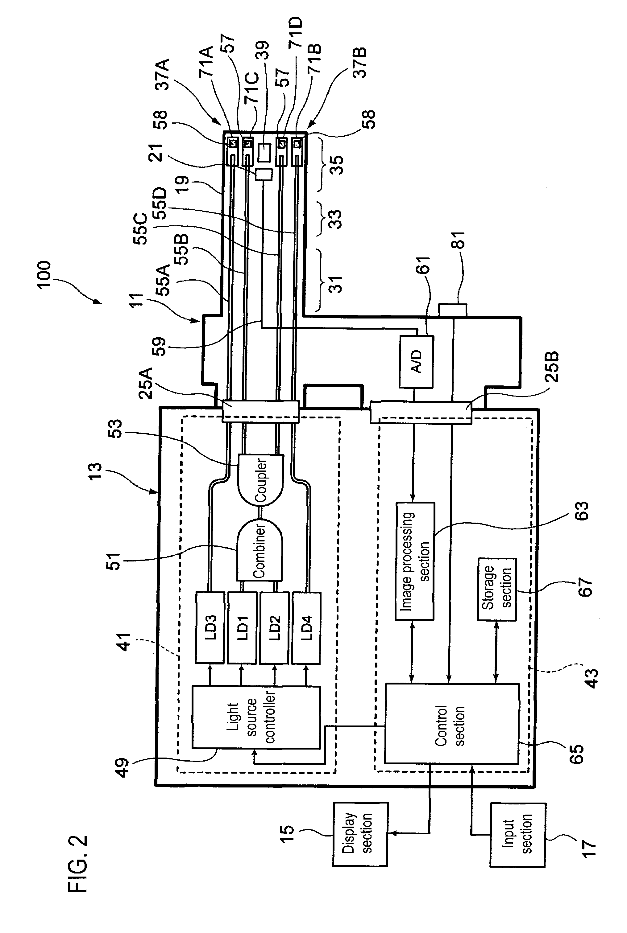
[0038]FIG. 1 is an appearance view showing an example of an endoscope apparatus according to an embodiment of the invention. FIG. 2 is a conceptual block diagram of the endoscope apparatus.

[0039]As shown in FIGS. 1 and 2, an endoscope apparatus 100 that is one medical equipment has an endoscope 11 and a control device 13 to which the endoscope 11 is connected. The control device 13 is connected with a display section 15 that displays image information and an input section 17 that receives an input operation. The endoscope 11, which is an electronic endoscope, has an illumination optical system that emits illumination light from a leading end of an endoscope insertion portion 19, which is inserted into an object to be examined, and an imaging optical system that includes an imaging device which images an area to be observed.

[0040]Also, the endoscope 11 has the endoscope inser...


PUM


Abstract

A medical equipment includes an optical connector that detachably connects a plug to a receptacle provided in an equipment main body to optically connect a plug-side optical fiber fixed to the plug and a receptacle-side optical fiber fixed to the receptacle. The plug and the receptacle have plural engagement pairs each having a protrusion that protrudes in an insertion direction of the plug and an engagement part that is adapted to be engaged with the protrusion. Engagement beginning positions of the engagement pairs where the protrusions and the engagement parts begin to engage are different along the insertion direction. Each engagement pair has a narrower engagement gap between the protrusion and the engagement part than that between the protrusion and the engagement part of any pair which begin to engage earlier as the plug is inserted than the protrusion and the engagement part of each engagement pair.

Description

CROSS-REFERENCE TO RELATED APPLICATIONS[0001]This application claims the benefit of Japanese Patent Application No. 2010-17487, filed Jan. 28, 2010, the entire contents of which are hereby incorporated by reference, the same as if set forth at length.BACKGROUND OF THE INVENTION[0002]1. Technical Field[0003]The invention relates to a medical equipment and an endoscope apparatus.[0004]2. Description of Related Art[0005]There is an endoscope apparatus including an endoscope having an illumination optical system that emits illumination light from a leading end of an endoscope insertion portion to be inserted into an object to be examined, and a control apparatus to which the endoscope is connected. The control apparatus has a light source device that generates the illumination light and a video processor that performs image processing. A universal cord is connected to a main body portion of the endoscope. The universal cord is provided therein with signal lines that are connected to the...

Claims


Application Information

Patent Timeline
Patent Type & Authority Applications(United States)
IPC IPC(8): A61B1/07
CPCA61B1/00117G02B6/3821G02B6/3853A61B1/00126G02B6/4292A61B1/00128G02B6/3878
Inventor KAGAYA, HIROTOMIZUYOSHI, AKIRAIIDA, TAKAYUKI
Owner FUJIFILM CORP
Why Eureka
Try Eureka