Solid fuel unit which burns solid fuels together with their volatile gases

a solid fuel unit and volatile gas technology, applied in the direction of lump/pulverulent fuel feeder/distribution, combustion process, lighting and heating apparatus, etc., can solve the problems of inability to consume, inefficient combustion of high-calorie coal, and difficulty in reducing the efficiency of combustion, so as to achieve a low particle ratio in the chimney, maintain the effect of burning efficiency and reduce the amount of ash

Inactive Publication Date: 2011-12-29
IMANI EMMETT
View PDF8 Cites 7 Cited by
  • Summary
  • Abstract
  • Description
  • Claims
  • Application Information

AI Technical Summary

Benefits of technology

[0027]Another purpose of the invention is to obtain an environmentally friendly system by achieving burning efficiency and minimizing particle ratio in the chimney.
[0028]Another purpose of the invention is to have an automatic slag crusher and discharge system as another advantage of the combustion system. In this way, its burning efficiency is maintained, provides endurance, does not require an operator, provides healthy and clean operating environment, and does not need halting due to slag and ash.
[0029]Another purpose of the invention is to minimize halting and failure by examining failure and maintenance points. Way of operation is simplified and operation software is developed using PLC. Since it is extremely easy to operate and operated by automation, operator error is eliminated. It provides continuous and optimum efficiency.

Problems solved by technology

Various deficiencies are encountered in most of these systems.
In the prior burners, high calorie coal is used due to inefficient combustion.
However, its consumption is prohibited because its reserves are quickly exhausted and low calorie coal, which is easy to produce, can not meet the emission standards.
Since excessive fuel load is made in the prior systems, and due to the CO found in the chimney emission, a high amount of losses occur or stack gas losses occur due to burning low amount of coal with high rate of air.
In some burner systems, coal thickness is so high in some areas (formation of CO increases due to insufficient air) and so low in other areas (causes excessive air and increase of oxygen amount in the stack gas).
Efficiency of the burner is affected by air amount, uniformity, proportionality, homogeneous spreading, and controllability of the system and these conditions can not be achieved in the prior systems.
Most of the classical burners are picky about fuel.
They can combust only certain sizes of fuels and high dust level affects combustion efficiency in the classical burners and also many systems are not convenient for burning dust or they simply can not burn.
In coarse coal burners, efficiency is low, since the optimization of spreading of the coal is not uniform and the dust ratio is variable.
In general applications, feed controls are adjusted in a faulty manner and stack gas losses reach very high levels due to excessive air.
However, the burning and operation technique of these systems are not efficient enough, they have high costs and their first investment costs are also very high.

Method used


Image

  • Solid fuel unit which burns solid fuels together with their volatile gases
  • Solid fuel unit which burns solid fuels together with their volatile gases
  • Solid fuel unit which burns solid fuels together with their volatile gases

Examples


Embodiment Construction

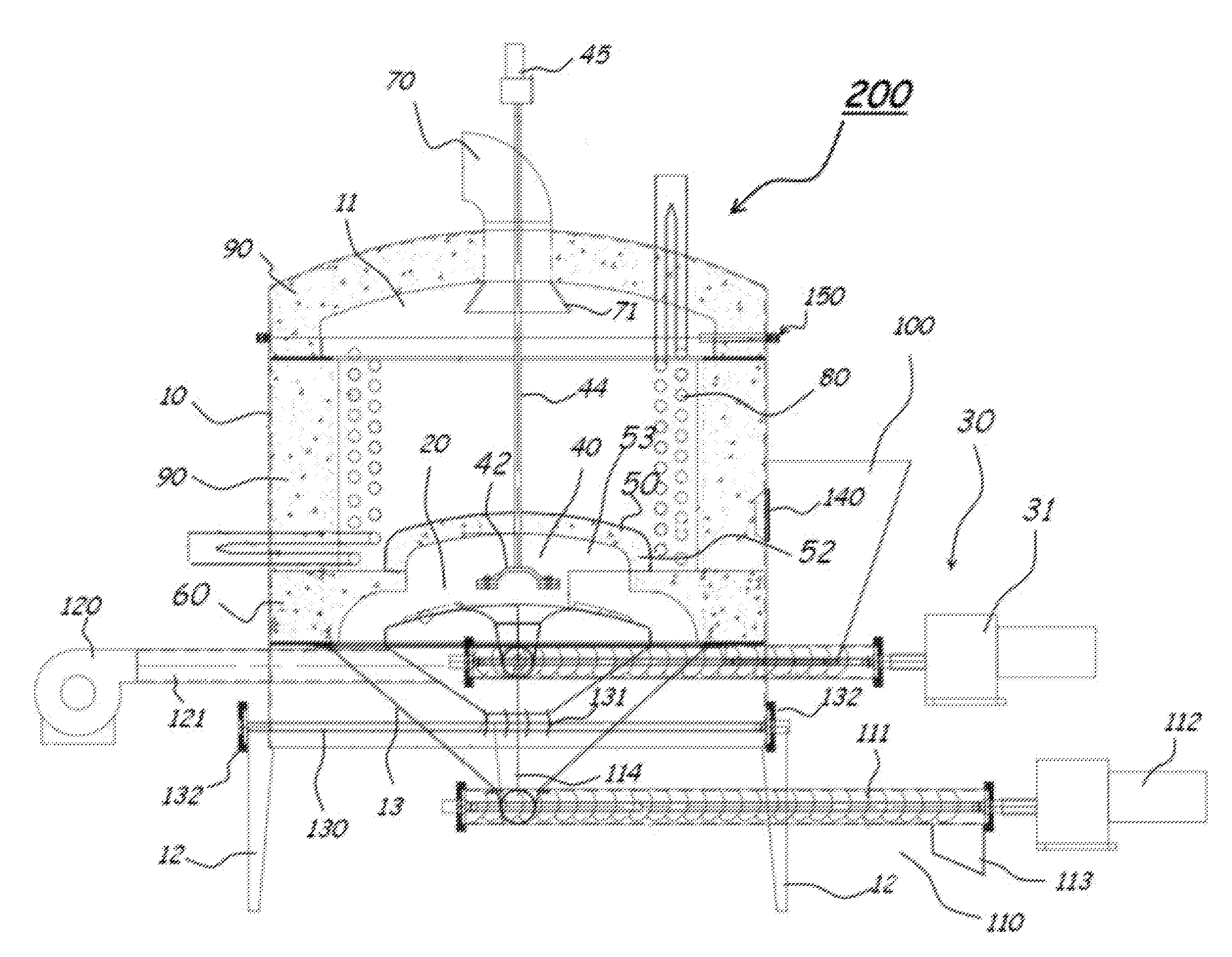
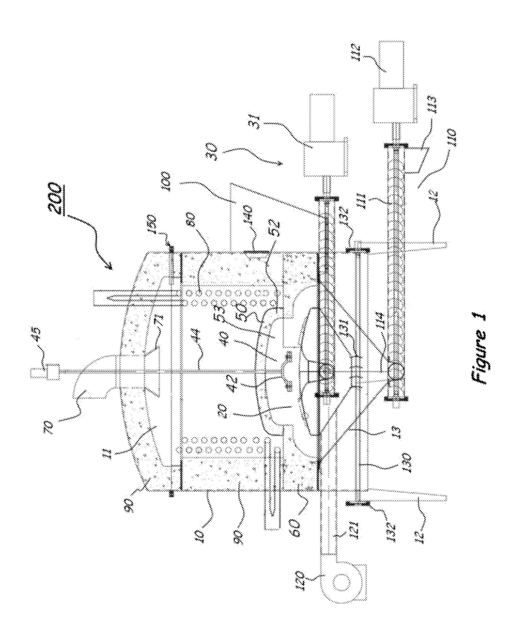
[0080]In FIG. 1, the two-dimensional section view showing all of the parts related to the solid fuel burning unit, which is the subject of the invention, is given.

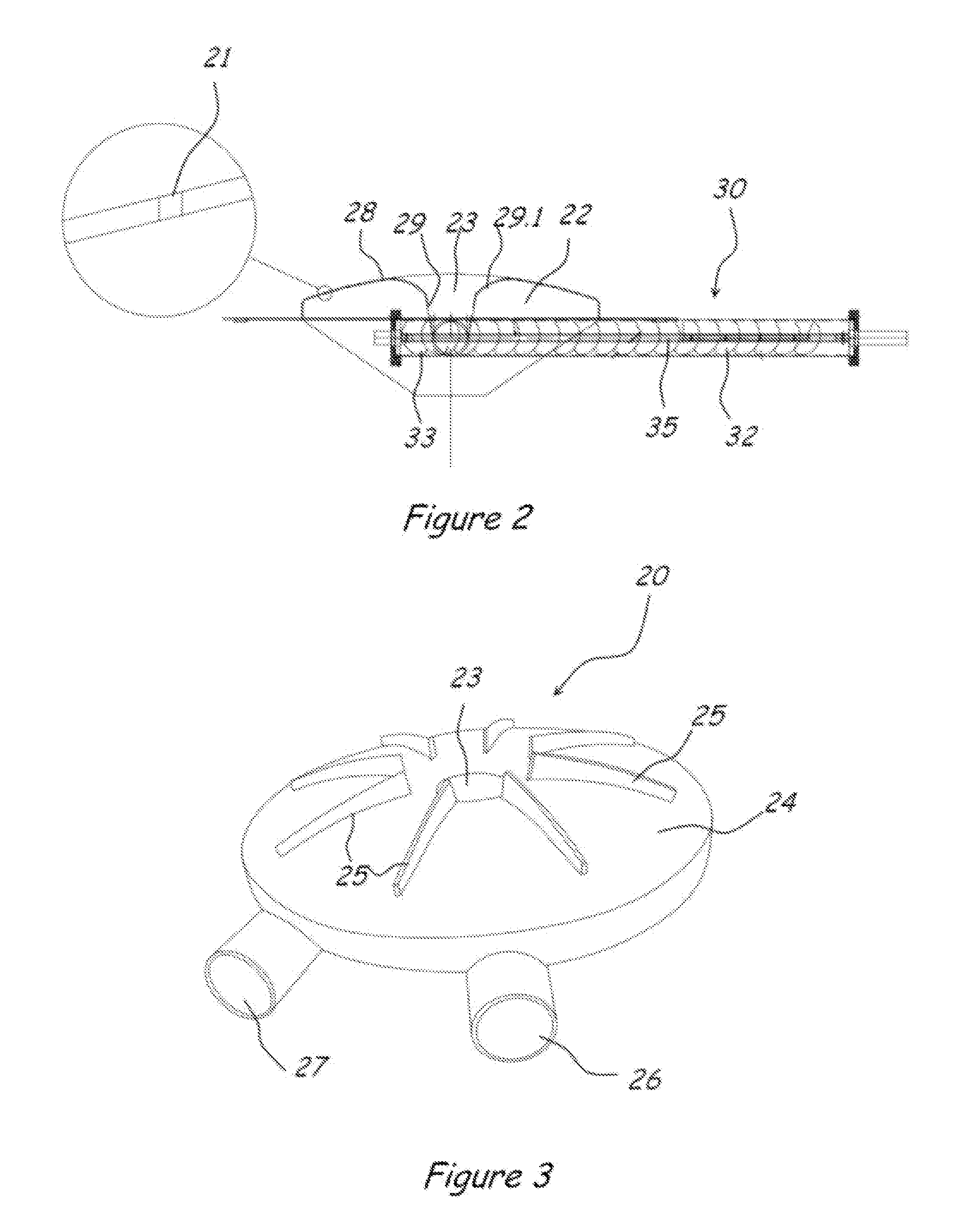
[0081]The invention relates to the solid fuel units (200) comprising a fuel supply chamber (100) wherein the fuel to be sent for combustion to the combustion region found in the body (10) is placed and the feed mechanism (30) carrying the solid fuel found in the said chamber (100) forward. It is characterized in that it comprises amain burning block (20) having a fuel and air cell (22) connected to the said solid fuel supply chamber (100) and air outlet vents (21) formed on the external wall surface (28), and a preventive surface (50) positioned on the said main burning block (20) external wall surface (28) in a way that it would form a closed volume in a certain distance.

[0082]The invention comprises at least one fuel discharge outlet (23) providing sending of the fuel, which is transferred to the said main burning block ...


PUM


Abstract

The invention relates to solid fuel units having a fuel supply chamber wherein the fuel to be sent for combustion to the combustion region found in the body is placed and the feed mechanism carrying the solid fuel found in the chamber forward. It is characterized in that it includes a main burning block having a fuel and air cell connected to the solid fuel supply chamber and air outlet vents formed on the external wall surface. A preventive surface is positioned on the main burning block external wall surface in a way that it would form a closed volume in a certain distance.

Description

RELATED U.S. APPLICATIONS[0001]Not applicable.STATEMENT REGARDING FEDERALLY SPONSORED RESEARCH OR DEVELOPMENT[0002]Not applicable.REFERENCE TO MICROFICHE APPENDIX[0003]Not applicable.FIELD OF THE INVENTION[0004]The invention relates to a solid fuel burning unit, by which the heated air, hot water, steam, and hot oil demands are met by burning coal, organic fuel, bagasse, nut shell, wood flour, rice stem etc. solid fuels, which are burned in industrial and domestic areas for production or heating purposes.[0005]The present invention relates to a solid fuel burning unit comprising a fuel supply chamber wherein the fuel to be sent for combustion to the combustion region found in the body is placed and the feed mechanism carrying the solid fuel found in the said chamber forward, amain burning block having fuel / air cell connected to the said solid fuel supply chamber and air outlet vents formed on the external wall surface. A preventive surface positioned on the said main burning block e...

Claims


Application Information

Patent Timeline
Patent Type & Authority Applications(United States)
IPC IPC(8): F23K3/00F23B40/00
CPCF23B40/04F23K3/14F23B10/02F23J1/00F23B80/04F23B30/00
Inventor OZYAMAN, SENOL FAIK
Owner IMANI EMMETT
Why Eureka
Try Eureka