Multifrequency Sieve Assembly for Circular Vibratory Separator

a vibratory separator and multi-frequency sieve technology, applied in the direction of sieving, solid separation, screening, etc., can solve the problems of low energy transfer to the sieve, material agglomeration, and ineffective conventional vibratory and tumbler separator methods and devices applied to certain materials

Active Publication Date: 2012-02-02
KROOSH TECH
View PDF6 Cites 26 Cited by
  • Summary
  • Abstract
  • Description
  • Claims
  • Application Information

AI Technical Summary

Benefits of technology

[0012]It is thus an aim of the present invention to provide an improved sieve assembly for vibratory or tumbler separator capable for sizing of fine and ultra-fine powder as well

Problems solved by technology

It is widely known, that conventional vibratory and tumbler separator methods and devices are generally ineffective when applied to certain materials, such as fine and highly cohesive powders, wet and sticky bulk materials, fiber materials and generally, so-called “difficult-to-screen” materials because the sieves used for sieving of such materials are prone to clogging and blinding and materials have a significant tendency to agglomerate.
Disadvantages of these systems include relatively low energy transfer to the sieve, insufficient de-agglomeration and sifting of “difficult-to-screen” materials.
Disadvantages of this system include relatively low energy transfer to the sieve fabric and insufficient de-agglomeration efficiency.
Also the cost of ultrasonic systems is high together with current expenses on frequent r

Method used


Image

  • Multifrequency Sieve Assembly for Circular Vibratory Separator
  • Multifrequency Sieve Assembly for Circular Vibratory Separator
  • Multifrequency Sieve Assembly for Circular Vibratory Separator

Examples


Embodiment Construction

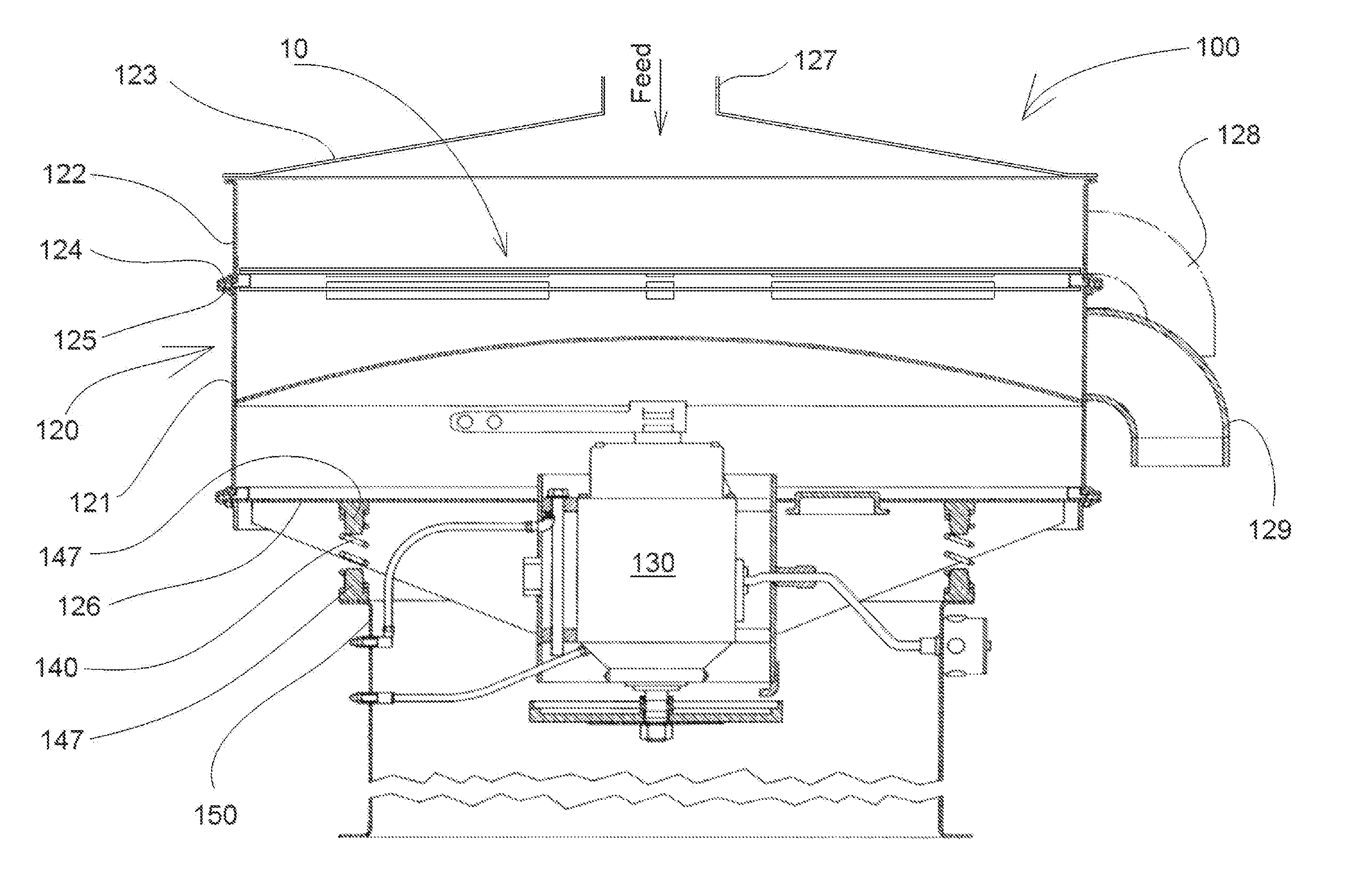
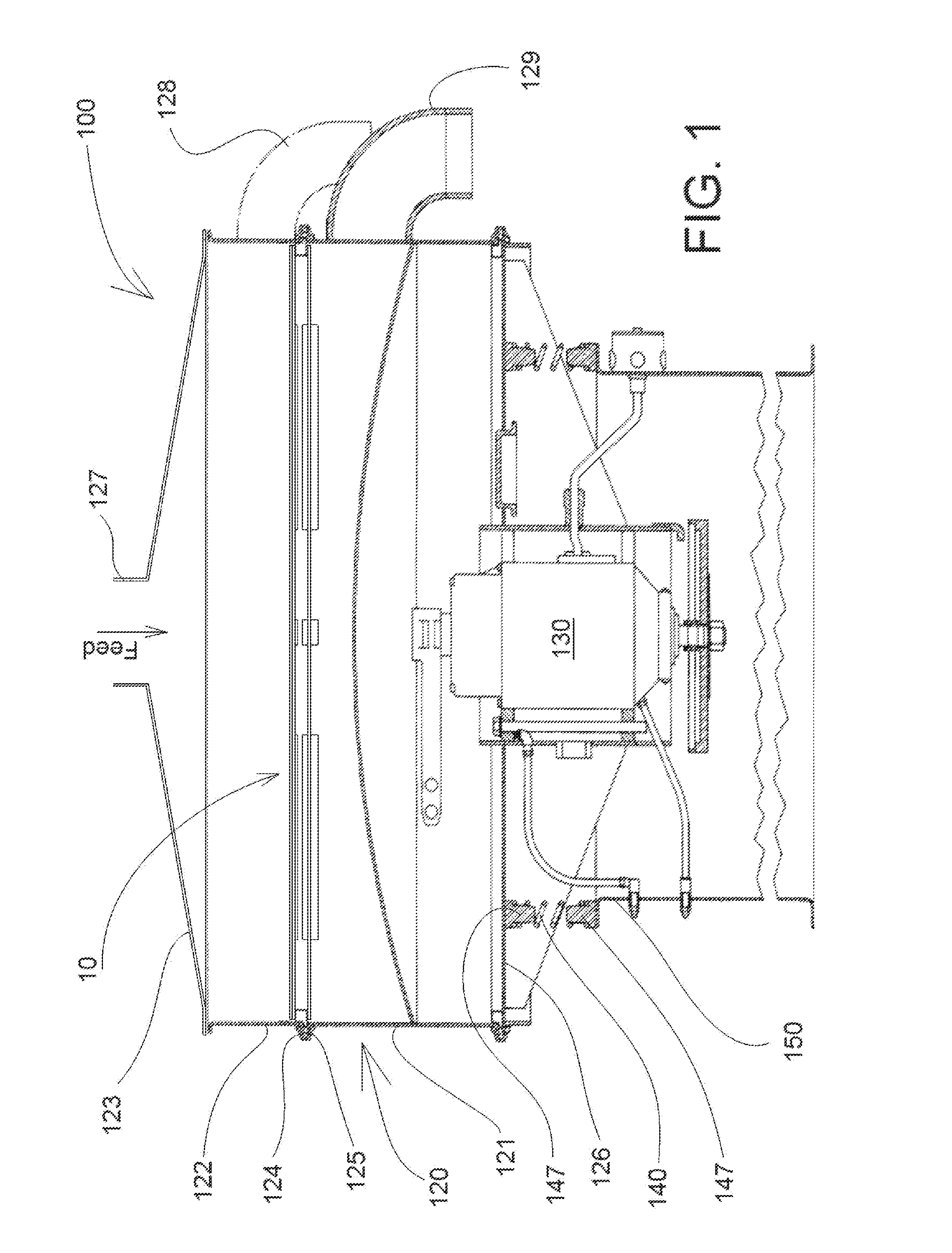
[0056]Referring now to FIG. 1, there is shown a typical one motor circular vibratory separator, referenced generally 100, driven by a single frequency centrifugal vibrator motor 130, however, employing multifrequency self-cleaning sieve assembly, referenced generally 10, constructed and operative in accordance with a preferred embodiment of the present invention. The present invention is intended primarily for screening of powder and bulk materials having a tendency to agglomerate and block sieve surface, and which typically have a particle size in the range from 0.01 to 500 microns.

[0057]The separator 100 includes a vibratable housing, referenced generally 120, having a cover 123, a screen assembly 10 clamped in housing 120 between undersize shell 121 and oversize shell 122, and a vibratory motor or exciter 130, mounted onto base plate 126 of housing 120. Motor 130 is typically any suitable single frequency vibratory motor having an operating rotation speed in the range 1000-3600 r...


PUM


Abstract

The invention is intended for sizing separation of difficult-to-screen powder materials and slurries. A sieve assembly includes a rigid frame, attached inside the separator housing, and upper and bottom sieves, stretched on the frame. The interface apparatuses are connected to the upper sieve, while actuator means—to the bottom sieve. The forced frequency of the vibrator is close to one of the natural frequencies of the bottom sieve. When the vibrator is operated, the actuator means interact with interface apparatuses, thus generating repeated collisions therebetween and mechanical impulses, which provide multifrequency excitation of the interface apparatuses and upper sieve. This ensures continuous self-cleaning of the upper sieve, intense loosening of the material bed and disintegration of the particle agglomerates. Separation capacity and products' quality substantially rises. In other embodiments presented sieve assembly includes buffer elements and inertial apparatuses, connected to the upper sieve.

Description

CROSS-REFERENCE TO RELATED APPLICATIONS[0001]This application is based on Russian patent application #2011137201 filed on Sep. 9, 2011 and two preceding Israeli patent applications: #203145, filed on Jan. 5, 2010 and # 214810, filed Aug. 24, 2011.FIELD OF THE INVENTION[0002]The present invention generally relates to material separation and, more particularly, to vibratory and tumbler sieve separation of particulate solids up to pre-selected sizes from a material having particles of different sizes, and including the separation of particles from bulk materials and from slurries.BACKGROUND OF THE INVENTION[0003]It is widely known, that conventional vibratory and tumbler separator methods and devices are generally ineffective when applied to certain materials, such as fine and highly cohesive powders, wet and sticky bulk materials, fiber materials and generally, so-called “difficult-to-screen” materials because the sieves used for sieving of such materials are prone to clogging and bli...

Claims


Application Information

Patent Timeline
IPC IPC(8): B07B1/36
CPCB07B1/54B07B1/38
Inventor KRUSH, IONAOBODAN, YURI
Owner KROOSH TECH
Why Eureka
Try Eureka