

Apparatus for heating service water
- Summary
- Abstract
- Description
- Claims
- Application Information
AI Technical Summary
Benefits of technology
Problems solved by technology
Method used
Image

Examples
Embodiment Construction
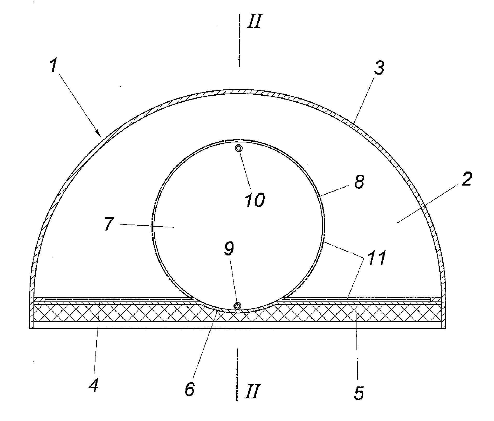
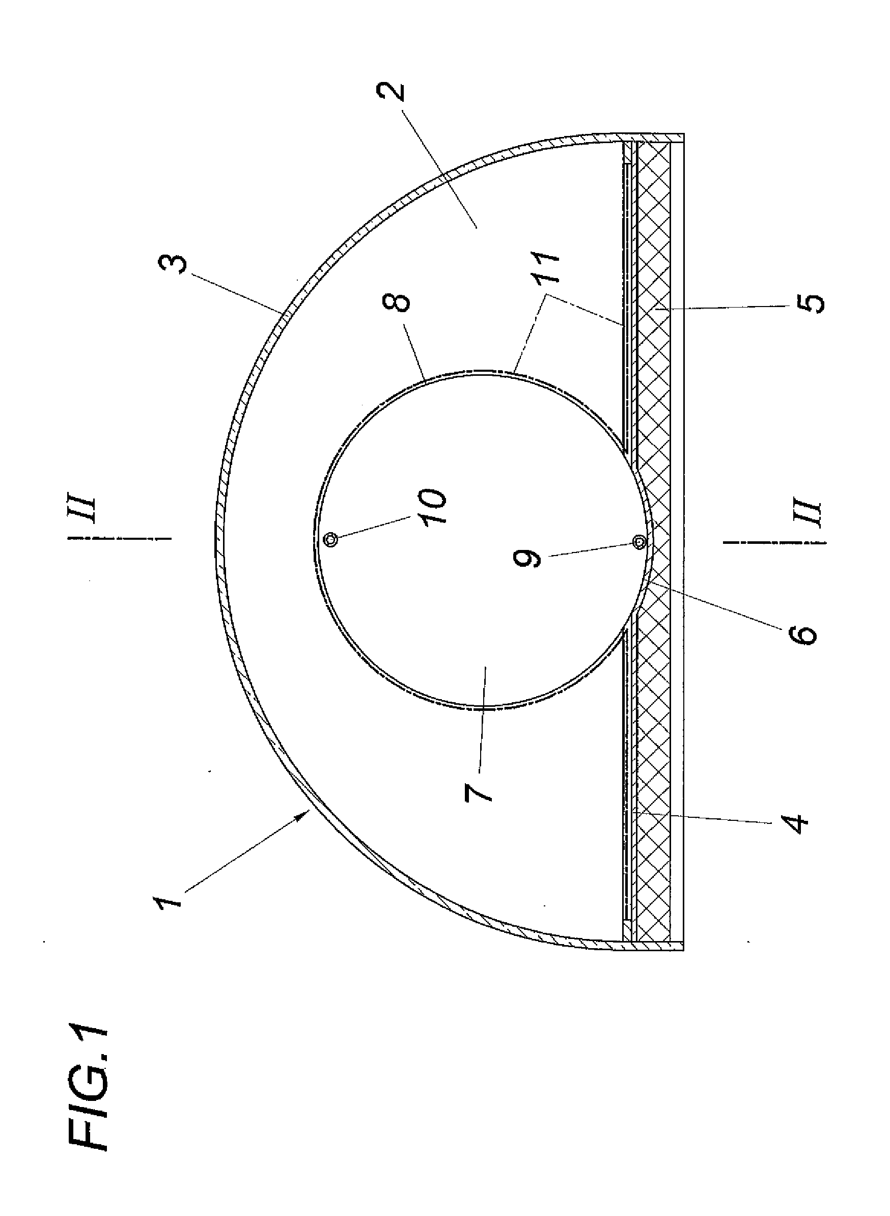
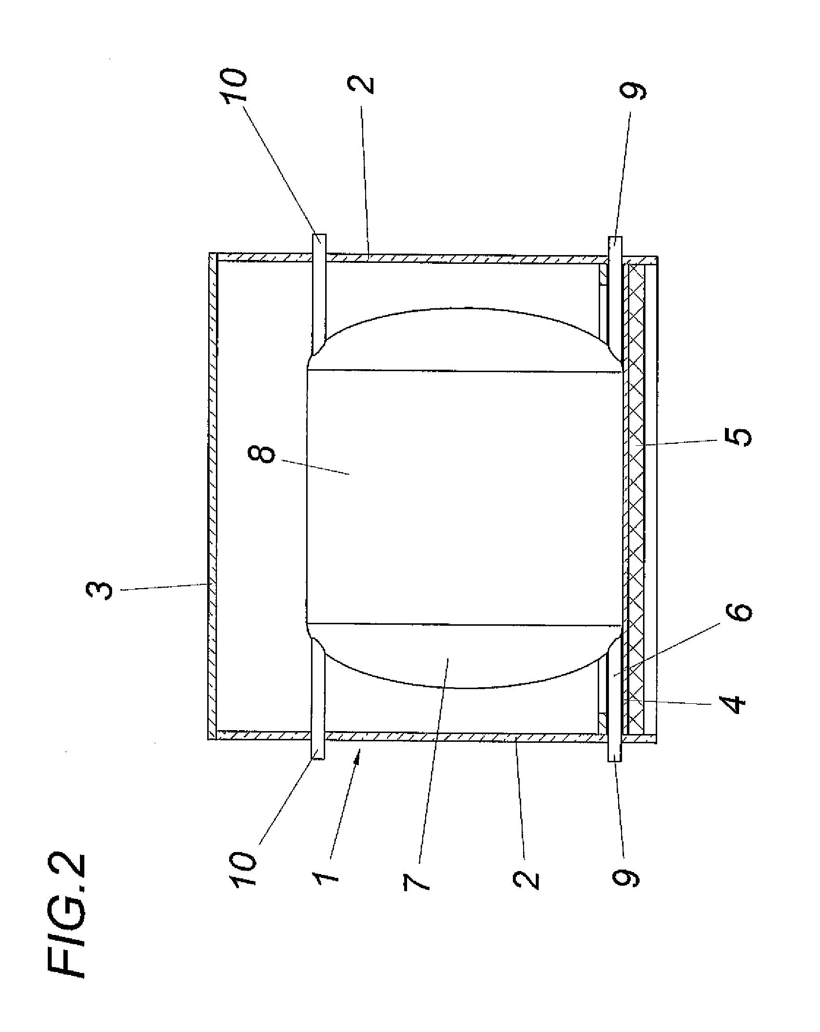
[0015]In accordance with the embodiment according to FIGS. 1 and 2, the apparatus for heating service water comprises a solar collector with an enclosure 1 which is composed of two semi-circular face walls 2 and a jacket 3 which is made of a translucent material and arched according to a half a circular cylinder. The bottom part of this enclosure 1 is formed by a thermally conductive absorber plate 4, which is preferably made of a metallic material such as copper or aluminum, and is provided with a thermal insulation 5 on the side facing away from the jacket 3. In the region of the cylinder axis of the enclosure 1, the absorber plate 4 forms a cylindrical bulging portion 6 which accommodates a horizontally disposed, cylindrical tank 7, the axis of which extends parallel to the axis of the enclosure 1. The arrangement is made in such a way that the jacket 8 of the service water tank 7 rests in a planar manner on the cylindrical bulging portion 6 of the absorber plate 4, which thereby...
PUM
 Abstract
Description
Claims
Application Information