Smart lighting system and method thereof

a technology of smart lighting and lighting systems, applied in the direction of lighting and heating apparatus, semiconductor devices for light sources, lighting support devices, etc., can solve the problems of increasing the initial cost of led lighting systems, and increasing the use of leds in major lighting applications. achieve the effect of reducing the amount of power

Inactive Publication Date: 2012-06-07
INNOVATIVE WIRELESS TECH
View PDF9 Cites 64 Cited by
  • Summary
  • Abstract
  • Description
  • Claims
  • Application Information

AI Technical Summary

Benefits of technology

[0014]Additionally, the lighting system herein may easily be configured to a video surveillance system in a residential building or larger group of buildings such as a university campus. Further, an emergency backup generator can provide emergency power to the lighting system in an event of a normal power failure.
[0017]In yet another aspect, the invention is a method of providing lighting over a relatively large area comprising the steps of: providing a plurality of LED lamps being an analogue of 100 W incandescent lamps; configuring a first microcontroller to the LED lamps; sensing a natural and an artificial light with a light sensor; dimming or brightening the plurality of LEDs based on the sensing using a PWM (pulse-width-modulated) current controller; providing a second microcontroller in wireless communication with the first microcontroller, wherein a user is able to remotely and programmably control system parameters via the second microcontroller.

Problems solved by technology

However, significant obstacles and disadvantages have prevented more widespread use of LEDs in major lighting applications.
Among these disadvantages are temperature sensitivity and also sensitivity to changes in voltage.
Also of significance, the initial cost of LED lighting systems is much more than incandescent or fluorescent systems partly due to the more complex drive circuitry required.

Method used


Image

  • Smart lighting system and method thereof
  • Smart lighting system and method thereof
  • Smart lighting system and method thereof

Examples


Embodiment Construction

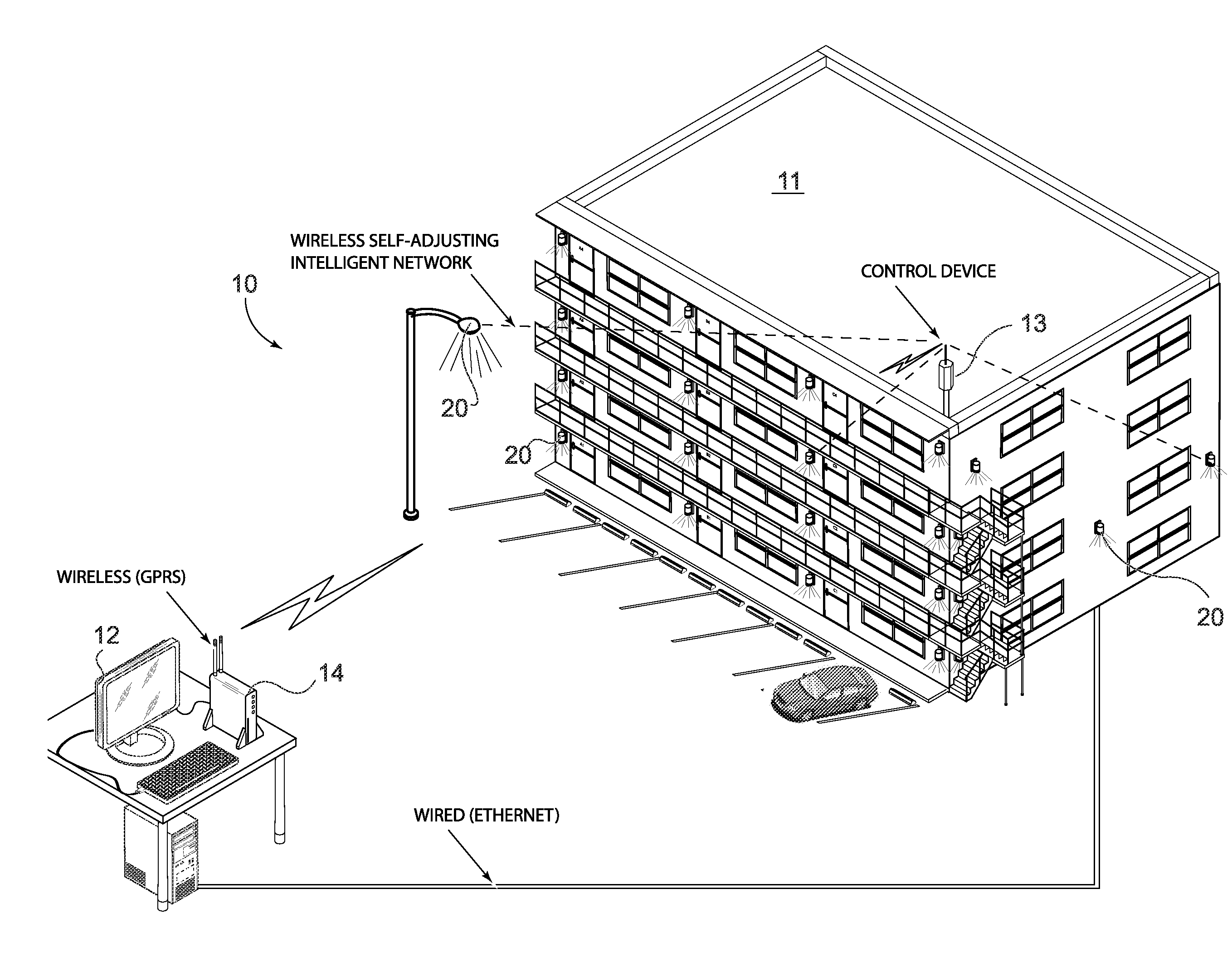
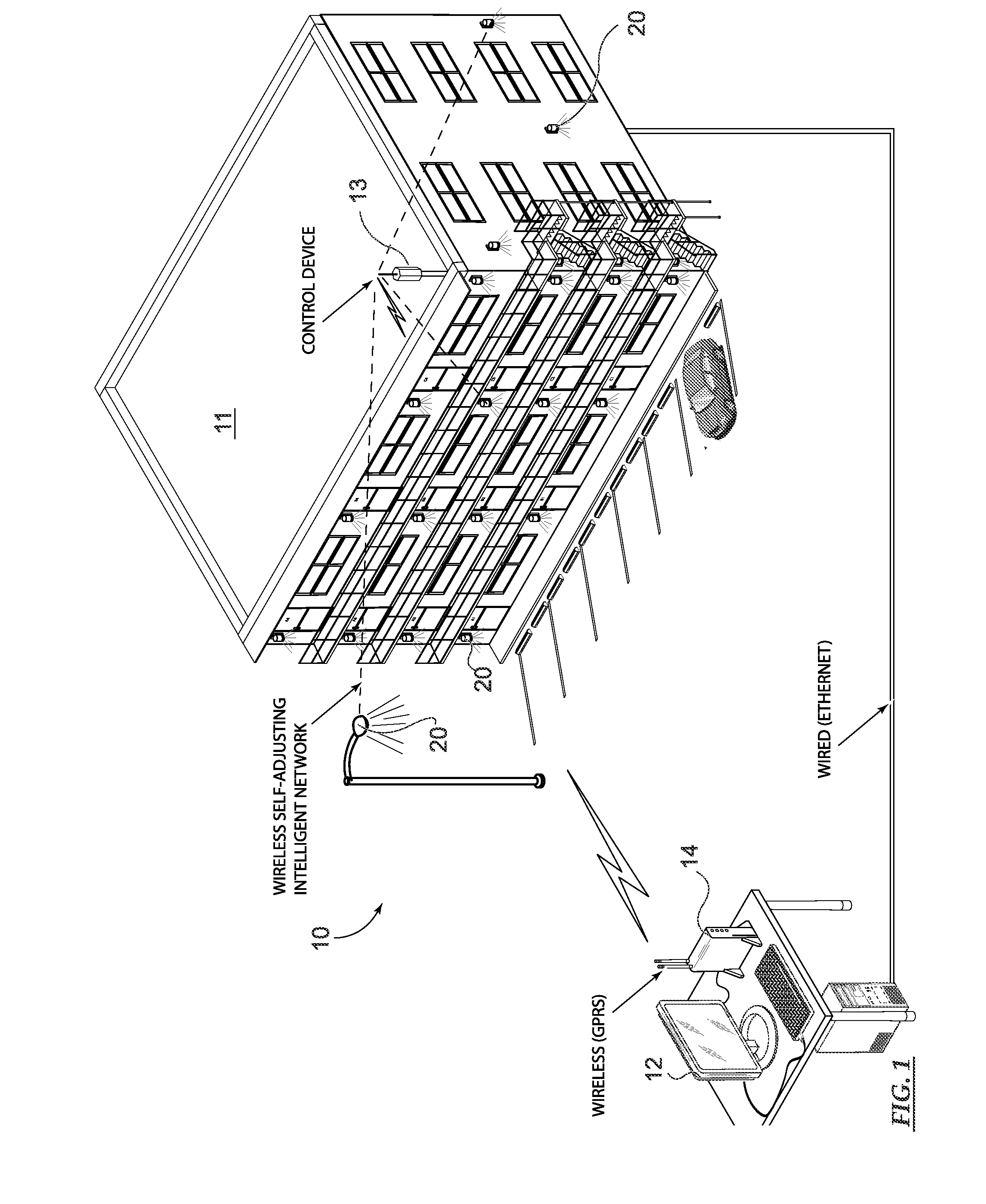
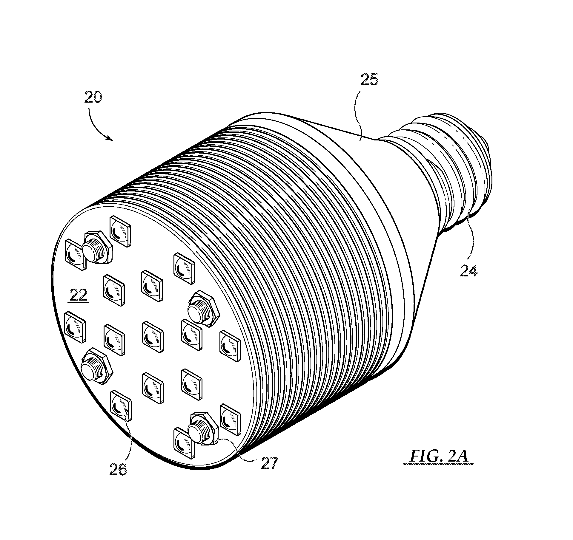
[0028]Initially with reference to FIG. 1, a schematical illustration is provided as an overview of a first preferred lighting system 10. It is envisioned that the system 10 can be ideal for residential or commercial buildings, a business park, shopping center, university campus etc. Further, the system 10 is programmable to provide a desired illumination as desired by a user. Also the system can programmably provide situational lighting since motion sensors are additionally configured to the present invention. Similarly, various light sensors 35 (FIG. 3B) are provided throughout a control area to provide input to a control microprocessor 13, 28. Alternatively, the light sensor and control microprocessor 28 can be integrated to the first PCB layer 21 of an individual LED lamp 20 (FIG. 2B). In yet another alternative, the first PCB layer has a built-in microprocessor and the remote microcontroller 13 is additionally configured to the internet wherein remote control is provided via a c...


PUM


Abstract

A programmable and remotely controlled lighting system employing LED lamps is disclosed herein. The system and methods of the present invention are ideally suited for residential or commercial buildings, court yards, business parks, universities, etc. Initially light sensors are provided to the system measuring available natural and artificial light. A system or area brightness is controlled programmably or remotely via a dimmer with PWM (pulse-width-modulated) power for reduced energy consumption. Wireless command and control is provided by microcontrollers with radio frequency transmitters and receivers. Additional circuitry is included to adequately compensate for transient input voltage. The lighting system further may be easily implemented to other systems able to be controlled by computer such as video surveillance systems and

Description

PRIORITY CLAIM[0001]This patent application contains subject matter claiming benefit of the priority date of U.S. Prov. Pat. App. Ser. No. 61 / 353,327 filed on Jun. 11, 2010, entitled SMART LIGHTING SYSTEM AND METHOD THEREOF; additionally this patent application contains subject matter claiming benefit of the priority date of U.S. patent application Ser. No. 12 / 537,111 filed on Aug. 6, 2009, entitled LIGHT CONTROL DEVICE, which contains subject matter claiming benefit of international patent application No. PCT / RU2008 / 000508 filed on Aug. 7, 2008.BACKGROUND OF THE INVENTION[0002]1. Field of the Invention[0003]The present invention relates generally to improvements in lighting systems allowing for energy savings and conservation of raw and manufactured materials. Additionally, the present invention generally relates to reducing costs to design and implement lighting systems and further lighting system designs capable of handling undesirable fluctuations in supply voltage. More particu...

Claims


Application Information

Patent Timeline
Patent Type & Authority Applications(United States)
IPC IPC(8): H05B37/02F21V29/00
CPCH05B33/0842H05B37/0272F21K9/13F21S2/00F21V23/006F21V29/89F21Y2101/02F21Y2105/001Y02B20/48F21V29/767F21V23/0435F21K9/23F21Y2105/10F21Y2115/10H05B45/325H05B45/37H05B47/19Y02B20/40
Inventor MIRONICHEV, SERGEI YURYEVICHALPATOV, PAVEL
Owner INNOVATIVE WIRELESS TECH
Why Eureka
Try Eureka