Floor covering system comprising a lighting system

a lighting system and floor covering technology, applied in the field of floor covering systems, can solve the problems of inconvenient cleaning of the system, inconvenient production, and infiltration of light sources or their housings into the carpet, and achieve the effect of reducing material use and being cheaper to produ

Active Publication Date: 2012-08-09
SIGNIFY HLDG BV
View PDF21 Cites 5 Cited by
  • Summary
  • Abstract
  • Description
  • Claims
  • Application Information

AI Technical Summary

Benefits of technology

[0018]An additional advantage of the present invention may be that the floor covering is protecting the lighting system that is underneath. Thus, when people are walking over the floor covering system, the floor covering may protect the lighting system from damage. Additionally, this may eliminate the need to use a protective housing for the lighting system, which may make the lighting system cheaper to produce.
[0019]Such floor covering system may be used in nearly any type of rooms or areas, such as living rooms, kitchens, bed rooms, play rooms, mud rooms, laundry rooms, aisles, shops, indoor training areas, garages, offices, schools, hotels, libraries, hospitals, transport vehicles (trains, boats, etc.), etc.
[0020]Such floor covering systems are arranged to provide floor light, i.e. light emanating from the floor covering when the lighting system is switched on. The floor light may be used to light rooms or areas, but may also be used as functional or decorative lighting. The floor light may alternatively or additionally also be used to provide information, like commercial information (trademarks, trade names, prices, etc.), other information (like time, temperature, date), and way finding information, such as directions for finding shops, rooms, entrances, exits, or areas. Especially, the floor covering system may be used to provide emergency way finding. Hence, the invention also provides the floor covering system as described herein for way guiding, especially for emergency way guiding. Therefore, such floor covering system may in an embodiment also be used to provide information by creating a lighting pattern on the floor (like an arrow, etc.).
[0021]The floor covering system according to the invention may comprise a wall-to-wall (or fitted) floor covering or a floor covering comprising a plurality of floor covering tiles. Hence, in an embodiment, the floor covering may comprise a plurality of PVC flooring tiles or a plurality of laminate flooring tiles (panels). The use of tiles may be advantageous, since in case a light source may need to be replaced, repaired or removed, only the relevant tile(s) may have to be removed (temporarily). In general, the tiles are arranged adjacent from each other, such that a closed floor covering is obtained. PVC and laminate floor covering tiles often have connectors, which allow plugging one tile in another tile. In this way, tiles can be “clicked” together; for instance, jigsaw-type of structures may be applied. Further, the lighting system may comprise a plurality of lighting units. This may provide freedom in where arranging light sources and may reduce use of material.
[0022]The lighting system in general comprises a plurality of light sources, especially LED (light emitting diode) light sources. The term “plurality of light sources” may refer to 2 or more light sources (especially LEDs), especially 2 to 100,000, for instance 2 to 10,000, like 4 to 300, such as 16 to 256. Hence, the lighting system may comprise a plurality of LEDs, such as 2 to 10,000 LEDs / m2, especially 25 to 2,500 LEDs / m2.
[0023]Note that the plurality of LEDs may be distributed over a plurality of lighting units. Thus, a lighting system may comprise one or more lighting units. In general, the lighting system will comprise a plurality of lighting units, depending upon the area to which the floor covering system is applied. The lighting units may be adjacent, or may be arranged at non-zero distances from each other. The lighting units may be powered independently or dependently. The lighting units may for instance be electrically interconnected. A controller (see below), may control one or more lighting units individually. The controller may (also) control one or more light sources individually.

Problems solved by technology

A disadvantage of many of the prior art is for instance that the light sources or their housing penetrate the carpet.
This may be undesired by users for reasons of aesthetics, because there is no “real broadloom” covering and there may be no constant covering feel and sight.
Additionally cleaning of the system may become more difficult, because the lighting system may need to be cleaned independent of the carpet.
Another problem of prior art may be that the cost is too high, and this cost is strongly increased by the housing required for the light sources.
Further, it may add to the complexity of the systems, which makes installation of the prior art light sources difficult.
Another disadvantage of prior art is that the lighting pattern cannot easily be changed after the system has been installed.

Method used


Image

  • Floor covering system comprising a lighting system
  • Floor covering system comprising a lighting system
  • Floor covering system comprising a lighting system

Examples


Embodiment Construction

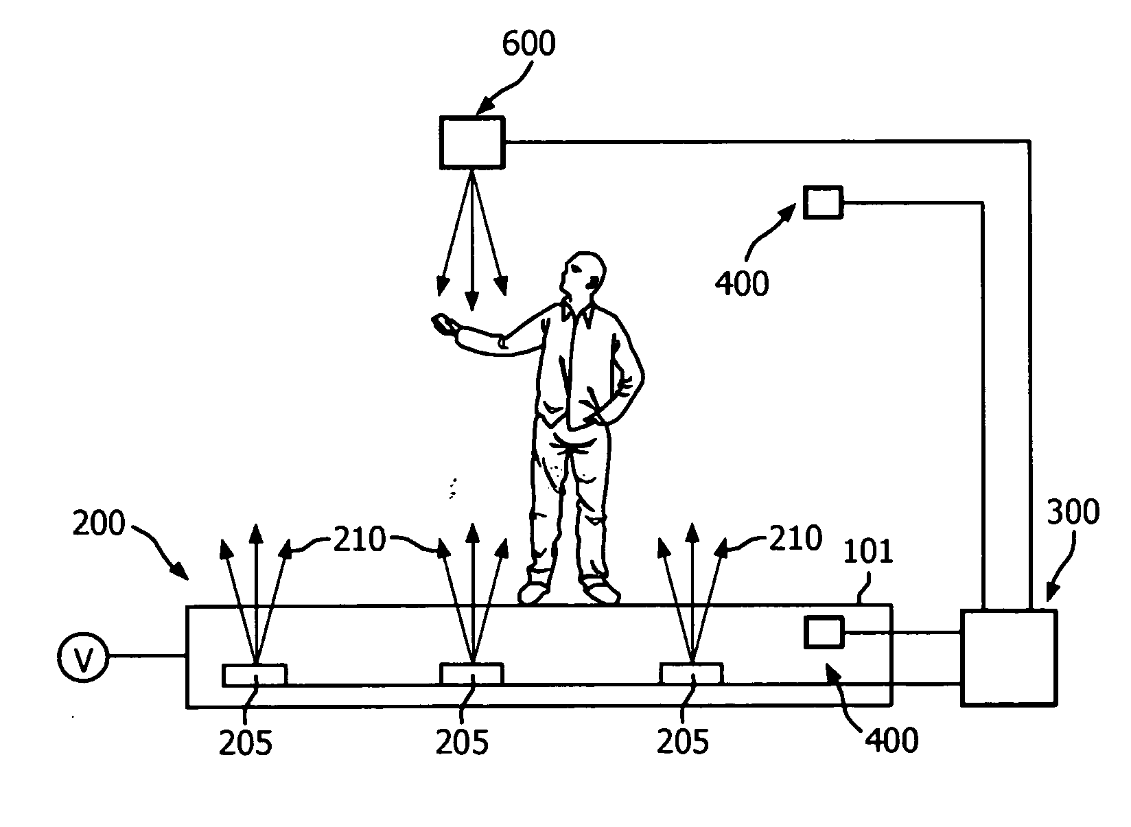
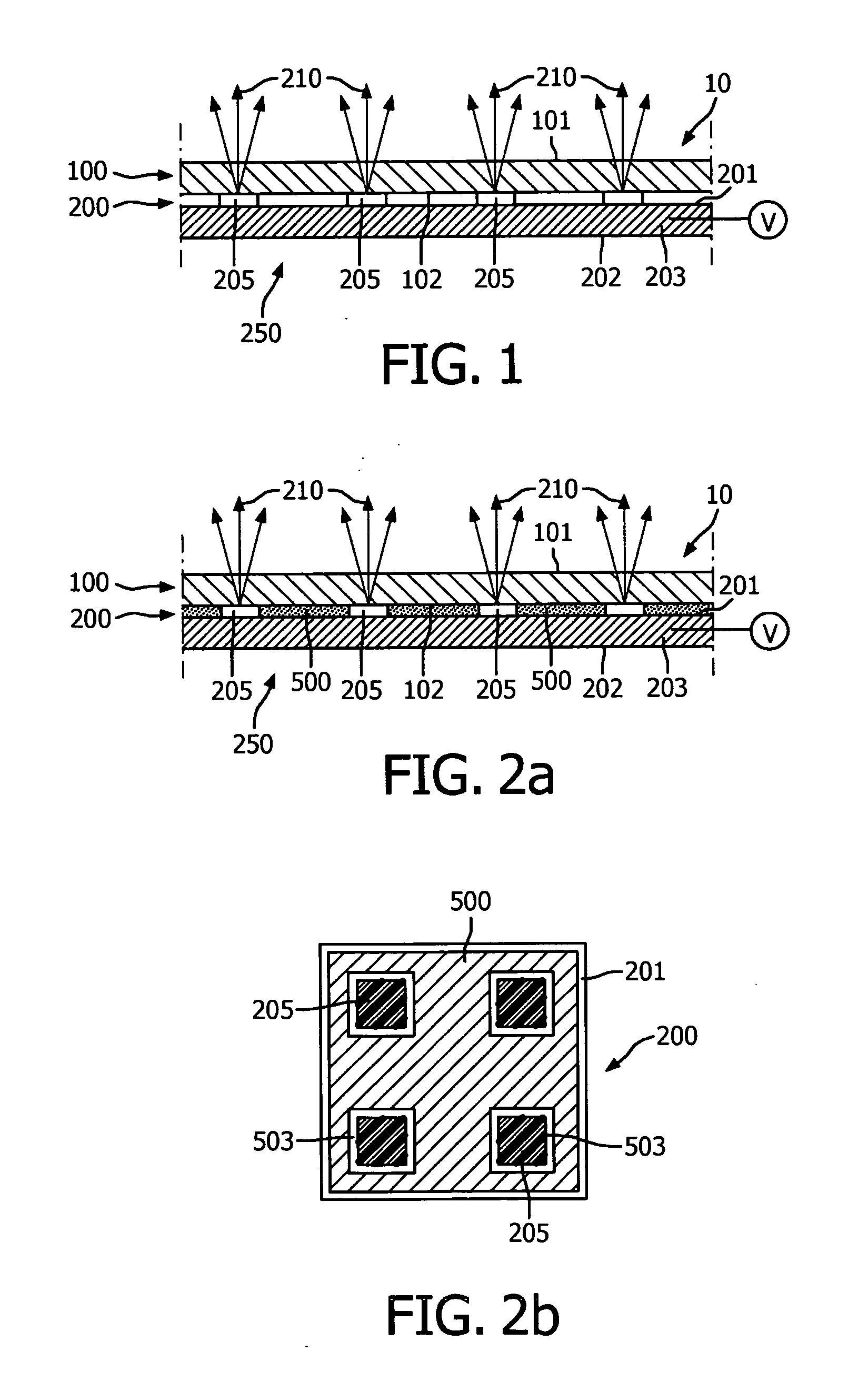
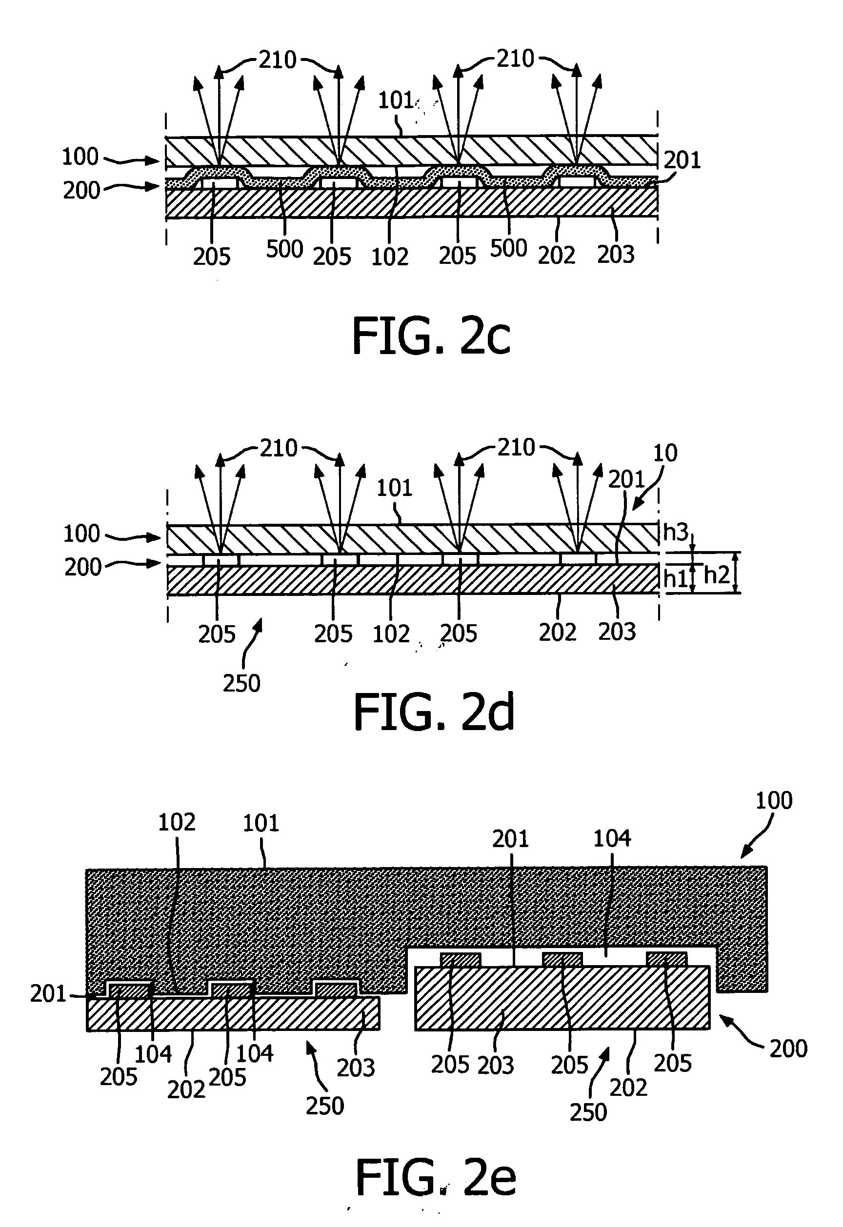
[0057]FIG. 1 schematically depicts an embodiment of a floor covering system 10 according to the present invention. The floor covering system 10 comprises (a) a floor covering 100 and (b) a lighting system 200 arranged to generate light 210.

[0058]The floor covering 100 has a user side 101 and an opposite back side 102. The lighting system 200 has a top side 201 and a bottom side 202. The lighting system 200 is arranged at the back side 102 of the floor covering 100. As can be seen in FIG. 1, the top side 201 of the lighting system 200 and the back side 102 of the floor covering 100 are facing each other. The back side 102 may also be indicated as illumination side. The lighting system 200 in this embodiment comprises a plurality of light sources 205, such as LEDs. The lighting system 200 is arranged to generate light 210 (when switched on). In this embodiment, the lighting system 200 comprises one lighting unit 250 (i.e. the lighting unit is the lighting system); in general the light...


PUM


Abstract

The invention provides a floor covering system (10) with (a) a PVC-based floor covering (100) and (b) a lighting system (200) arranged to generate light (210). The PVC-based floor covering (100) has a user side (101) and an opposite back side (102). The lighting system (200) is arranged at the back side (102) of the PVC-based floor covering (100). The PVC-based floor covering (100) has a light transmission for light (210) generated by the lighting system (200) in the range of 0.5% to 30%, especially in the range of 1% to 20%.

Description

FIELD OF THE INVENTION[0001]The invention relates to a floor covering system comprising a floor covering having a user side and an opposite back side, and a lighting system provided at the back side of the floor covering[0002]The invention also relates to a floor covering and a floor covering tile for use in the floor covering system.[0003]The invention further relates to a method for providing the floor covering system, and to the use of the floor covering system for way guiding.BACKGROUND OF THE INVENTION[0004]Lighting on or in floors is known in the art. EP0323682 for instance describes an apparatus for guiding the occupants of a building along a path of travel within the building which comprises modular carpet tiles which are arranged to cover the floor of the structure, with some of the tiles being signal units having a light-transmissive, moulded plastics housing positioned in an opening therein, and having light-emitting diodes positioned in the housing. The light-emitting di...

Claims


Application Information

Patent Timeline
Patent Type & Authority Applications(United States)
IPC IPC(8): F21S8/00
CPCE04F15/02F21V33/006F21V23/0442E04F2290/026
Inventor VAN HERPEN, MAARTEN MARINUS JOHANNES WILHELMUSWILLEMSEN, OSCAR HENDRIKUSKRIJN, MARCELLINUS PETRUS CAROLUS MICHAEL
Owner SIGNIFY HLDG BV
Why Eureka
Try Eureka