Control circuit and method for a ripple regulator system

a ripple regulator and control circuit technology, applied in the field of ripple regulator systems, can solve the problems of cot ripple regulator systems almost impossible to operate stably, adverse loop stability, specific conditions, etc., and achieve the effect of improving the output offset of a ripple regulator system, small ripples, and high loop stability

Active Publication Date: 2012-08-30
RICHTEK TECH
View PDF0 Cites 34 Cited by
  • Summary
  • Abstract
  • Description
  • Claims
  • Application Information

AI Technical Summary

Benefits of technology

[0006]An objective of the present invention is to provide a control circuit and method for a ripple regulator system to have small ripples and high loop stability simultaneously.
[0007]Another objective of the present invention is to provide a control circuit and method for improving the output offset of a ripple regulator system.
[0008]According to the present invention, a control circuit for a ripple regulator system includes an error comparator to compare a reference voltage with a feedback voltage related to the output voltage of the ripple regulator system to generate a comparison signal, a PWM controller to trigger a PWM signal responsive to the comparison signal to control an inductor current, a ripple generation circuit to provide a ripple signal in-phase and synchronous with the inductor current to be superposed to the reference voltage or the feedback voltage for improving the loop stability, and an offset cancellation circuit to extract a ripple information proportional to the amplitude of the ripple signal from the ripple generation circuit, to generate an offset cancellation signal for the error comparator to improve the offset of the output voltage caused by the ripple signal.
[0009]According to the present invention, a control method for a ripple regulator system includes comparing a reference voltage with a feedback voltage related to the output voltage of the ripple regulator system to generate a comparison signal for triggering a PWM signal to control an inductor current, generating a ripple signal in-phase and synchronous with the inductor current to be superposed to the feedback voltage or the reference voltage, and extracting a ripple information proportional to the amplitude of the ripple signal to generate an offset cancellation signal for improving the offset of the output voltage caused by the ripple signal.

Problems solved by technology

Large ripples are beneficial to loop stability; however, they may result in over specification conditions.
On the contrary, small ripples could remain the system under specifications, while they are adverse to loop stability.
Thus, it is a challenge to maintain loop stability with small output voltage ripples for design of the power converter system.
However, in the case that a ceramic capacitor is used as the output capacitor Co, due to the very small effective series resistance R3 of the ceramic capacitor, the output voltage Vout and thereby the feedback voltage Vfb1 will have very small ripples, even could be regarded as DC signals, causing the COT ripple regulator system almost impossible to operate stably.

Method used


Image

  • Control circuit and method for a ripple regulator system
  • Control circuit and method for a ripple regulator system
  • Control circuit and method for a ripple regulator system

Examples


Embodiment Construction

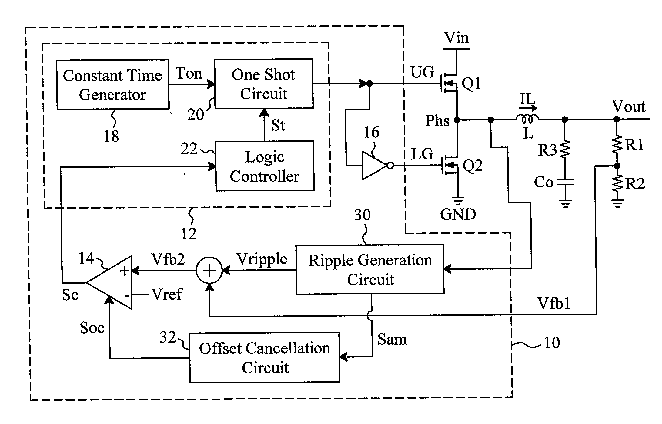
[0017]FIG. 3 is a circuit diagram of an embodiment according to the present invention based on the circuit shown in FIG. 1, in which the output capacitor Co has a very small effective series resistance R3 and thus makes the feedback voltage Vfb1 have small ripples that can be regarded as a DC signal, as shown by the waveform 36 in FIG. 4. In addition to the PWM controller 12, error comparator 14 and inverter 16 as those shown in FIG. 1, the control circuit 10 shown in FIG. 3 further includes a ripple generation circuit 30 and an offset cancellation circuit 32. According to the voltage at the phase node Phs, the ripple generation circuit 30 generates a ripple signal Vripple in-phase and synchronous with the inductor current IL for a positive input terminal of the error comparator 14. In particular, the ripple signal Vripple is superposed to the feedback voltage Vfb1 to generate a feedback voltage Vfb2 having large ripples, as shown by the waveform 34 in FIG. 4, thereby preventing the...


PUM


Abstract

A control circuit and method for a ripple regulator system generate a ripple signal in-phase and synchronous with an inductor current of the ripple regulator system, and extract a ripple information proportional to the amplitude of the ripple signal. The ripple signal is used for triggering control in PWM signal generation to make the ripple regulator system have small ripples and better loop stability simultaneously. The ripple information is used to improve the output offset of the ripple regulator system that is caused by the ripple signal.

Description

FIELD OF THE INVENTION[0001]The present invention is related generally to a ripple regulator system and, more particularly, to a control circuit and method for a ripple regulator system.BACKGROUND OF THE INVENTION[0002]In a constant on time (COT) or hysteretic mode self-clocking DC-to-DC power converter system, generation of the pulse width modulation (PWM) signal relies on ripples of the output voltage to carry out triggering control. Large ripples are beneficial to loop stability; however, they may result in over specification conditions. On the contrary, small ripples could remain the system under specifications, while they are adverse to loop stability. Thus, it is a challenge to maintain loop stability with small output voltage ripples for design of the power converter system.[0003]As shown in FIG. 1, a traditional COT ripple regulator system includes a high-side device Q1 and a low-side device Q2 connected to each other by a phase node Phs in series between a voltage input ter...

Claims


Application Information

Patent Timeline
Patent Type & Authority Applications(United States)
IPC IPC(8): G05F1/10
CPCH02M2001/0025H02M3/156H02M1/0025H03K7/08G05F1/40
Inventor CHEN, AN-TUNGYANG, CHIH-HAO
Owner RICHTEK TECH
Why Eureka
Try Eureka