
Playback apparatus, program, and playback method
a technology of video output and playback method, which is applied in the direction of read-only discs, television systems, instruments, etc., can solve the problems of user complaints about products, disordered display or interruption of monitors,
- Summary
- Abstract
- Description
- Claims
- Application Information
AI Technical Summary
Benefits of technology
Problems solved by technology
Method used
Image

Examples
embodiment 1
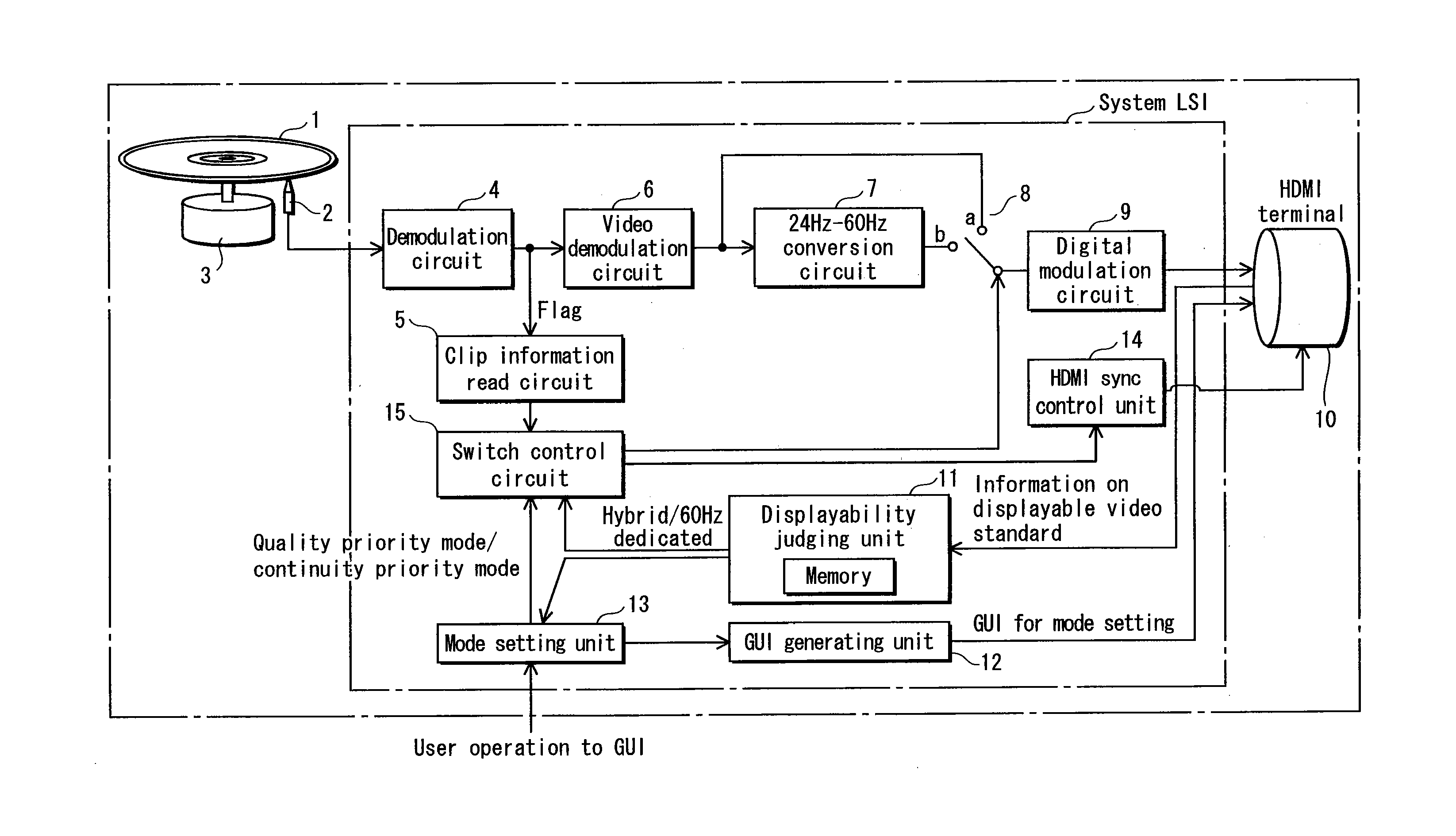
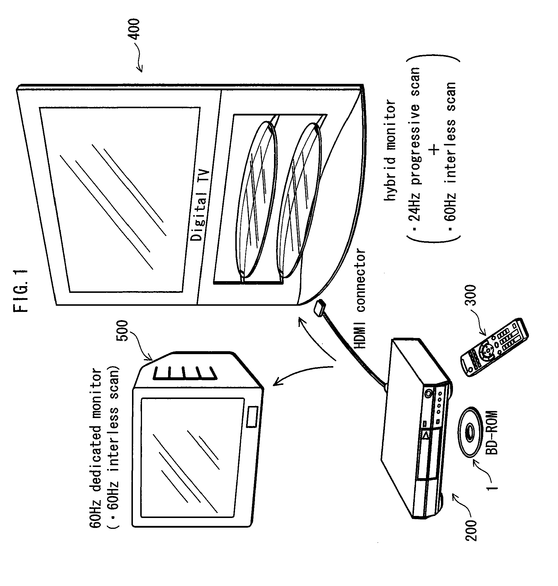
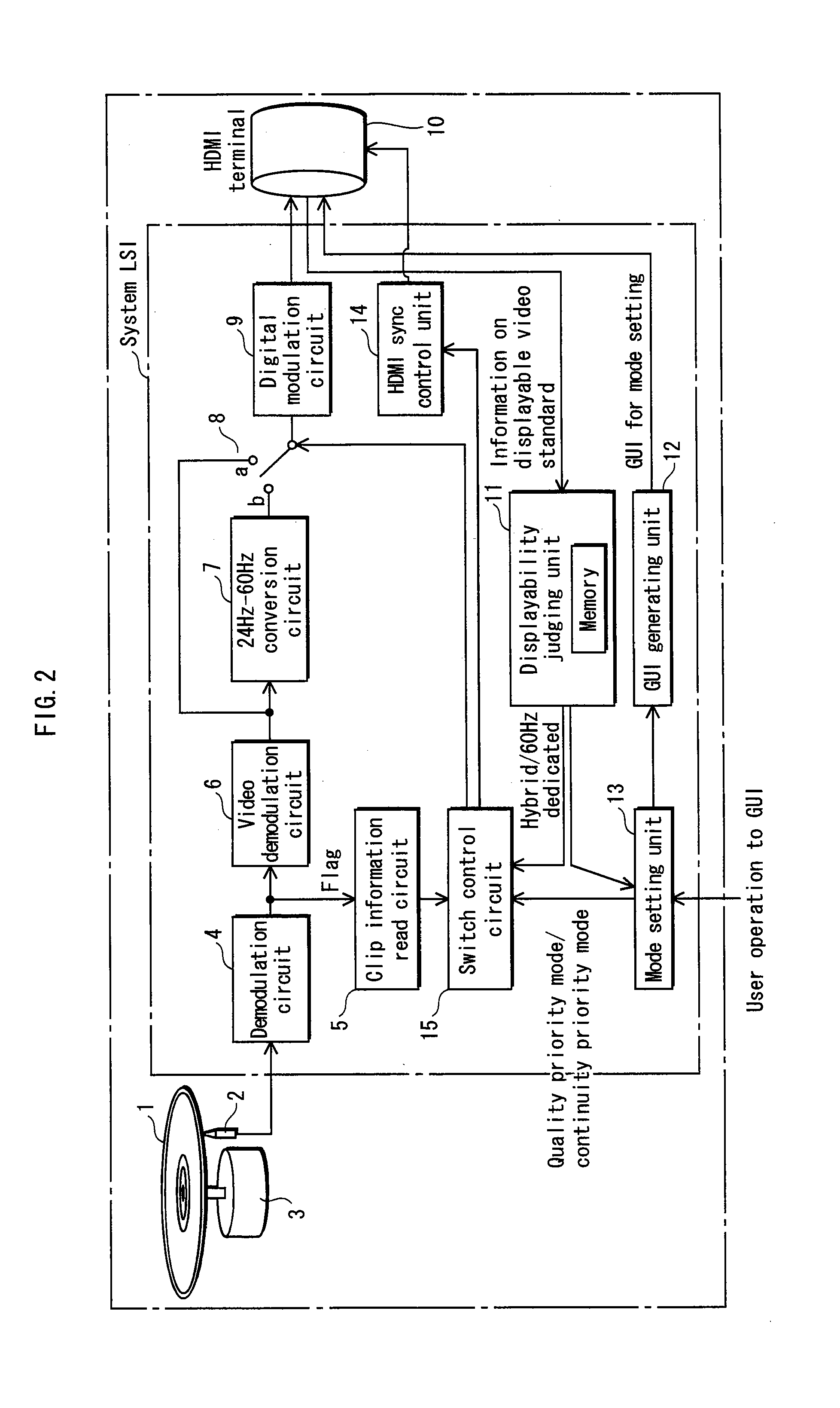
[0047]First, among various aspects of the playback apparatus of the present invention, the use form will be described. In FIG. 1, the playback apparatus of the present invention is a playback apparatus 200 which is used in a home theater system that further includes a remote controller 300, a hybrid monitor 400, and 60 Hz dedicated monitor 500.
[0048]The playback apparatus 200 reproduces a video signal recorded on an optical disc 1. The playback apparatus outputs an interlace video signal of 60 frames / sec (hereinafter referred to as “60 Hz interlace signal”) and a progressive video signal of 24 frames / sec, as video outputs. The playback apparatus has a digital output terminal, and sends these video signals to the hybrid monitor 400 and the 60 Hz dedicated monitor 500 via an HDMI connector.
[0049]The hybrid monitor 400 can display the 60 Hz interlace signal and the progressive video signal.
[0050]The 60 Hz dedicated monitor 500 can display the 60 Hz interlace signal.
[0051]Up to now, the...
embodiment 2
[0150]In Embodiment 2, it is presumed that a multi-frame monitor is used. The multi-frame monitor is a monitor that displays images at a scan frequency in accordance with an instruction provided from the playback apparatus. In Embodiment 2, the multi-frame monitor scans at 48 Hz, which is an integral multiple of 24 (frames / sec), during a video playback. The video signals recorded on films are suitable for display at 24 frames / sec as described in Embodiment 1. However, a flickering may occur during a display at 24 frames / sec. In movie theaters, the film is moved so that each frame is exposed to light twice to avoid such a flickering. Accordingly, if the playback apparatus plays back the video signal at 48 frames / sec in the present embodiment, the quality of the displayed image is close to the quality of the image displayed in the movie theater.
[0151]The following describes the internal structure of the playback apparatus in Embodiment 2. FIG. 17 shows the internal structure of the pl...
embodiment 3
[0166]In Embodiment 3, as is the case with Embodiment 2, it is presumed that a multi-frame monitor is used. The multi-frame monitor is a monitor that displays images at a scan frequency in accordance with an instruction provided from the playback apparatus. In Embodiment 3, the multi-frame monitor scans at 72 Hz, which is an integral multiple of 24 (frames / sec), during a video playback.
[0167]The following describes the internal structure of the playback apparatus in Embodiment 3. FIG. 21 shows the internal structure of the playback apparatus in Embodiment 3. FIG. 21 is based on the internal structure of the playback apparatus of Embodiment 2 shown in FIG. 17. The difference from FIG. 17 is that the 24 Hz-48 Hz conversion circuit 21 has been replaced with a 24 Hz-72 Hz conversion circuit 24. Also, with the addition or replacement of the structural elements, the displayability judging unit 11 and the switch control circuit 15 perform the following processes that are unique to Embodime...
PUM
 Abstract
Description
Claims
Application Information