Evaporative fuel treatment apparatus of vehicle

Inactive Publication Date: 2012-09-20
HONDA MOTOR CO LTD
View PDF14 Cites 5 Cited by
  • Summary
  • Abstract
  • Description
  • Claims
  • Application Information

AI Technical Summary

Benefits of technology

[0030]According to the evaporative fuel treatment apparatus for a vehicle in an embodiment of the present invention, the fuel push the pressing plate upward and hence the seal member is collapsed in the vertical direction, whereby the seal member is protruded toward the fuel supply gun insertion hole and is brought into tight contact with the fuel supply gun to seal the gap. Therefore, the gap is sealed by the seal member pushed upward by the liquid surface and collapsed thereby, and hence the liquid trap between the reverse flow preventing valve and the pressing plate can be used as the liquid seal even in the vicinity of the fuel supply port. Also, since the seal member is brought into tight contact with the fuel supply gun by being collapsed by the liquid surface at the time of fuel supply, and the seal member and the fuel supply gun do not come into sliding contact with each other when inserting or pulling out the fuel supply gun, the sealing property of the seal member can be prevented from being affected by the inserting and pulling-out operation, so that the sealing property of the seal member can be ensured.
[0031]Also, since the fuel supply gun insertion hole of the seal member is formed to have a diameter equal to or larger than that of the fuel supply gun insertion hole of th

Problems solved by technology

However, as described in JP-A-8-91062 shown above, a configuration in which the liquid seal is formed by providing the liquid trap portion in the fuel supply pipe can be applied to a passenger vehicle which allows for provision of a long fuel supply pipe, but it is difficult to provide the liquid trap portion on fuel tanks of motorcycles or l

Method used


Image

  • Evaporative fuel treatment apparatus of vehicle
  • Evaporative fuel treatment apparatus of vehicle
  • Evaporative fuel treatment apparatus of vehicle

Examples


first embodiment

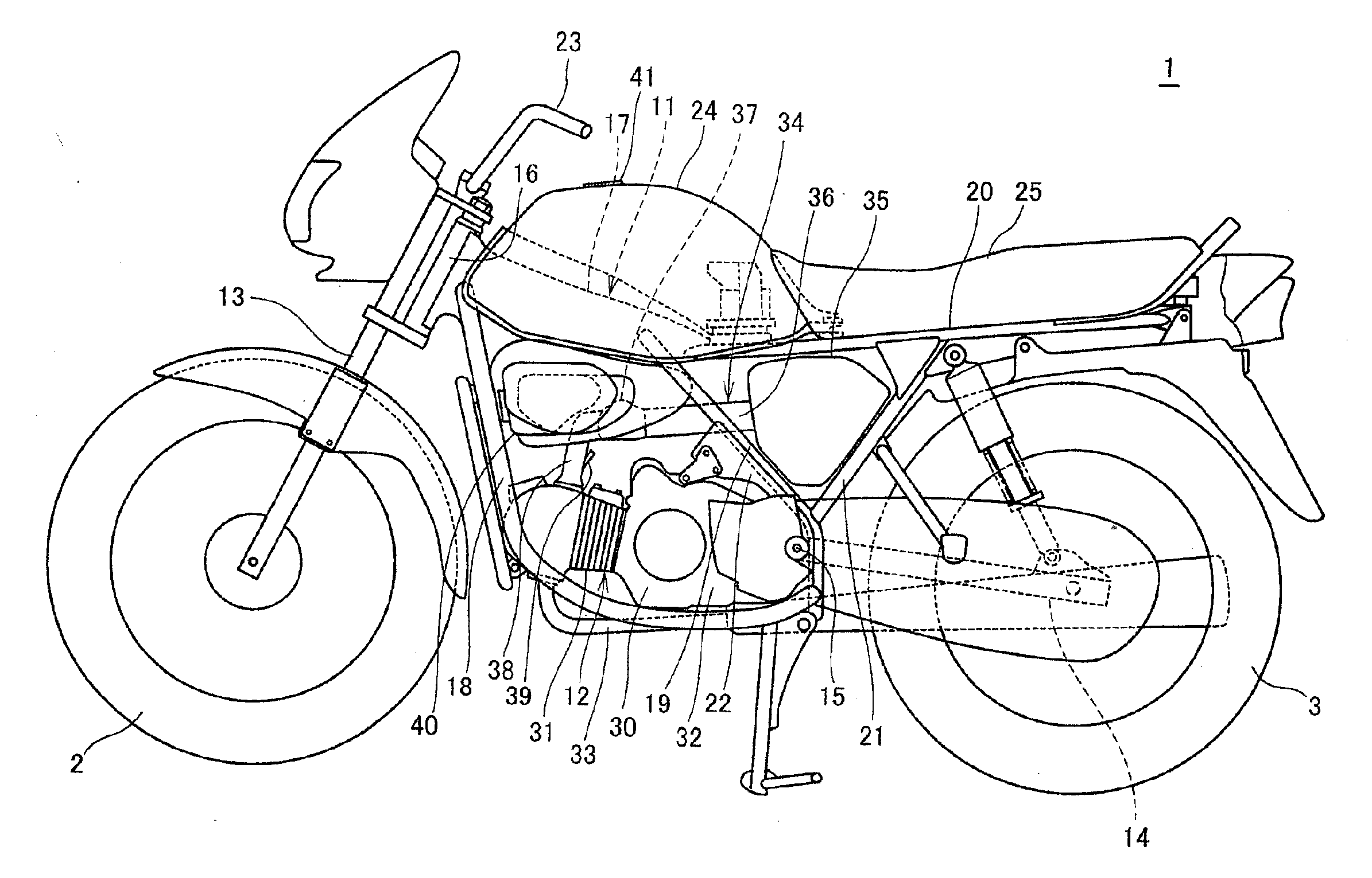
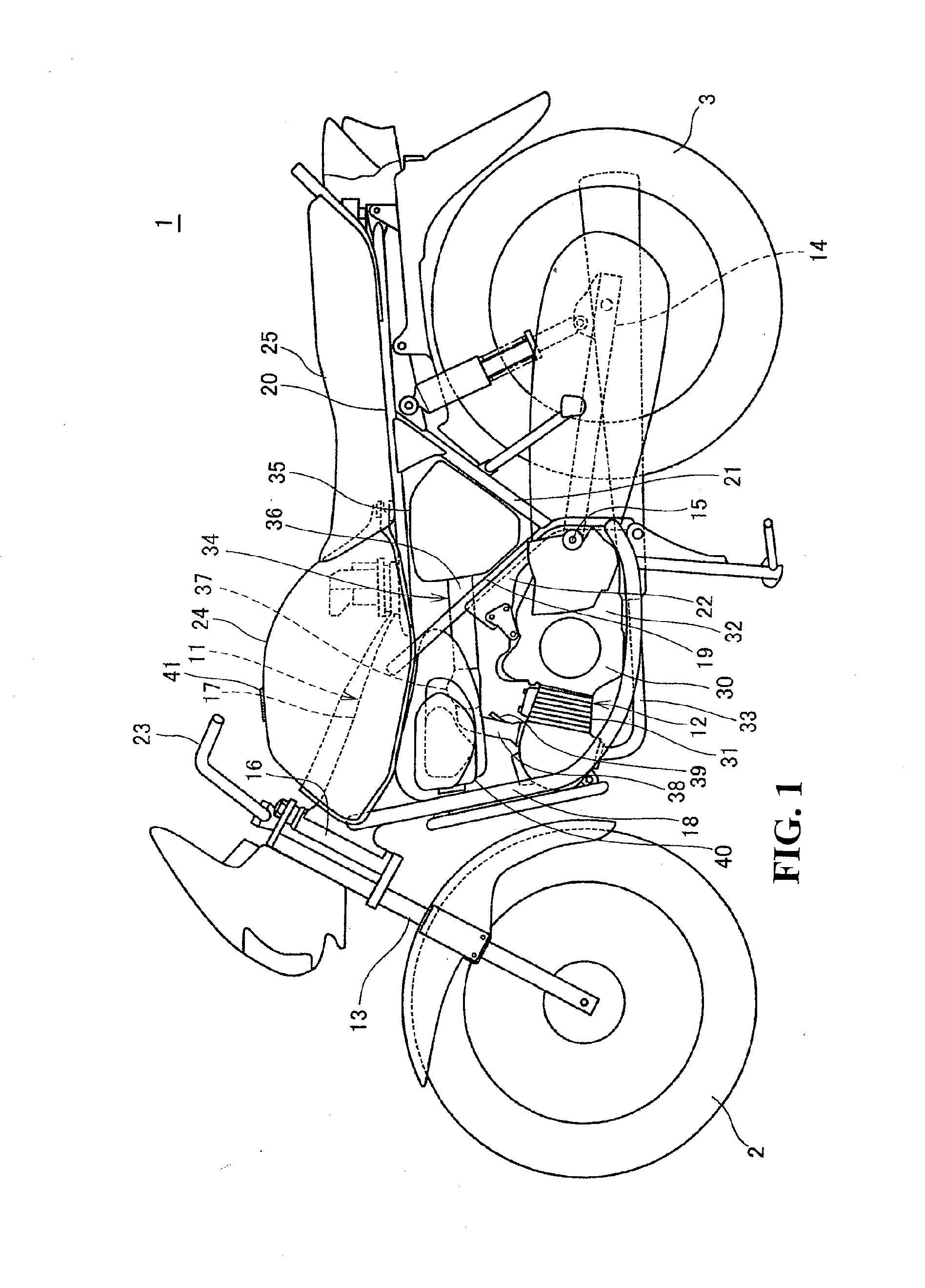
[0046]FIG. 1 is a left side view of a motorcycle according to an embodiment of the present invention.

[0047]A motorcycle 1 (vehicle) is a saddle-type vehicle including an engine 12 (internal combustion engine) arranged at a center of a vehicle body frame 11 in the fore-and-aft direction, front forks 13 configured to support a front wheel 2 supported at a front end of the vehicle body frame 11 so as to be steerable, and a rear swing arm 14 configured to support a rear wheel 3 and provided at a lower rear portion of the vehicle body frame 11.

[0048]The vehicle body frame 11 includes a head pipe 16 configured to support a pair of the left and right front forks 13 so as to be steerable, a main frame 17 extending rearward and downward from a rear portion of the head pipe 16, a pair of left and right down frames 18 extending rearward and downward from a lower portion of the head pipe 16, a pair of left and right center frames 19 extending downward from a rear portion of the main frame 17, a...

second embodiment

[0096]Referring now to FIG. 6, a second embodiment of the present invention will be described. In the second embodiment, portions configured in the same manner as those in the first embodiment are designated by same reference numerals and descriptions thereof are omitted.

[0097]In the description of the first embodiment, the seal member 65 having a sponge form is collapsed in the vertical direction between the pressing plate 64 and the positioning plate 63, and protrudes toward the fuel supply gun insertion hole 65A to achieve sealing. However, the second embodiment is different from the first embodiment in that fuel enters a bag-shaped seal member 265 and the seal member 265 protrudes to achieve sealing.

[0098]FIG. 6 is a cross-sectional view showing a configuration of a seal mechanism 260 according to the second embodiment.

[0099]The seal mechanism 260 includes the fuel supply pipe 61, the reverse flow preventing valve 62, the positioning plate 63, a lower plate 264 provided in the f...


PUM


Abstract

An evaporative fuel treatment apparatus for a vehicle is provided with a reverse flow preventing valve provided in a fuel supply pipe, a positioning plate provided on the fuel supply pipe, a pressing plate mounted slidably on the fuel supply pipe between the positioning plate the reverse flow preventing valve, a seal member clamped between the positioning plate and the pressing plate, and a stopper. When the fuel supply is started, the reverse flow preventing valve is configured to be set opened so as to form a liquid trap between the reverse flow preventing valve and the pressing plate. When the liquid surface reaches the pressing plate, the fuel pushes the pressing plate upward and the seal member is collapsed in the vertical direction so that the seal member protrudes toward the fuel supply gun insertion holes and makes tight contact with the fuel supply gun to seal a gap.

Description

CROSS-REFERENCE TO RELATED APPLICATION[0001]The present application claims priority under 35 U.S.C. §119 to Japanese Patent Application No. 2011-057563, filed Mar. 16, 2011. The entire contents of the above-identified application are hereby incorporated by reference.BACKGROUND OF THE INVENTION[0002]1. Field of the Invention[0003]The present invention relates to an evaporative fuel treatment apparatus of a vehicle.[0004]2. Description of Background Art[0005]In the related art, at the time of fuel supply to a fuel tank of a vehicle, an evaporative fuel treatment apparatus configured to prevent evaporative fuel in the fuel tank from diffusing from a fuel supply port to the outside and to feed the evaporative fuel to an evaporative fuel storage container is disclosed (for example, see JP-A-8-91062 and JP-UM-A-5-32065).[0006]In JP-A-8-91062, a liquid seal is formed by a liquid trap portion provided at a midsection of a fuel supply pipe to prevent evaporative fuel in a fuel tank from diff...

Claims


Application Information

Patent Timeline
IPC IPC(8): F02M33/02
CPCF02M25/089B62J35/00B60Y2200/12B60K2015/03514
Inventor SHIMURA, TAKESHIIMAMURA, TAKAHIRO
Owner HONDA MOTOR CO LTD
Why Eureka
Try Eureka