Conveying unit and vacuum deposition device

a vacuum deposition device and conveying unit technology, applied in vacuum evaporation coating, web handling, transportation and packaging, etc., can solve the problems of reducing or varying the vacuum degree, affecting film deposition by a considerable amount, and it is extremely difficult to use gas contaminants in vacuum deposition devices, so as to reduce surface damage and deterioration of properties, and minimize the deterioration of film crystal growth

Inactive Publication Date: 2012-05-29
FUJIFILM CORP
View PDF8 Cites 2 Cited by
  • Summary
  • Abstract
  • Description
  • Claims
  • Application Information

AI Technical Summary

Benefits of technology

[0014]Use of the roller disclosed in JP 2000-86032 A can prevent damage to a sheet due to sliding contact between sheet and roller caused by variations in the speed or the pressing force with which the roller presses the sheet.
[0016]In general, both ends of a long sheet are rarely used as part of a product. Therefore, by using a stepped roller so that the central region of a sheet used as a product does not come in contact with the roller, damage to the sheet can be prevented as in the roller disclosed in JP 2000-86032 A.
[0018]The present invention has been made to solve the problems as described above, and an object of the present invention is to provide a conveying unit for conveying a long sheet-like subject (sheet) which is capable of considerably reducing damage to the sheet or deterioration of the surface properties due to sliding contact of the sheet with other members or pressing force irrespective of the width and weight of the sheet.
[0025]The conveying unit of the sheet-like subject (hereinafter simply referred to as the “sheet conveying unit”) of the present invention uses a stepped roller, which forms a chamber with a sheet to provide closed space between the stepped roller and the sheet and a gas is introduced into the closed space. Therefore, the present invention can prevent the central region of the sheet to be brought in sliding contact with the roller even if variations in speed or tension occur. The gas is introduced into the space between the stepped roller and the sheet to support the central region of the sheet by the gas pressure and therefore the sheet can be stably conveyed while advantageously preventing sliding contact between the sheet and the roller irrespective of the width and weight of the sheet.
[0027]The vacuum deposition device of the present invention that uses the sheet conveying unit of the present invention having the features as described above can form a film by vacuum deposition on a substrate having considerably reduced surface damage and deterioration of the properties while also preventing the sliding contact between the conveyor roller and the substrate and the situation in which the conveyor roller presses the substrate during the conveyance of the substrate in the vacuum chamber.
[0028]Accordingly, the vacuum deposition device of the present invention can form a proper film while minimizing the deterioration of the crystal growth of the film and occurrence of cracks and missing parts in the film due to the damage to the substrate surface and the deteriorated surface properties, thereby producing a product having the intended performance in a consistent manner.

Problems solved by technology

Since the conveyor roller always discharges air during conveyance of the sheet, the conveyor roller, when used in the above-described vacuum deposition device, may decrease or vary the degree of vacuum or cause gas contaminants to considerably adversely affect film deposition.
Therefore, it is extremely difficult to use it in the vacuum deposition device.
However, in cases where a stepped roller is used, a wide sheet or a sheet with a large weight has slack or wrinkles in the central region of the sheet (in its width direction) to destabilize conveyance and the sheet may often have damage or deterioration in the surface properties due to contact or sliding contact with the roller.

Method used


Image

  • Conveying unit and vacuum deposition device
  • Conveying unit and vacuum deposition device
  • Conveying unit and vacuum deposition device

Examples


Embodiment Construction

[0033]Next, the conveying unit and the vacuum deposition device according to the present invention are described in detail by referring to the preferred embodiments shown in the accompanying drawings.

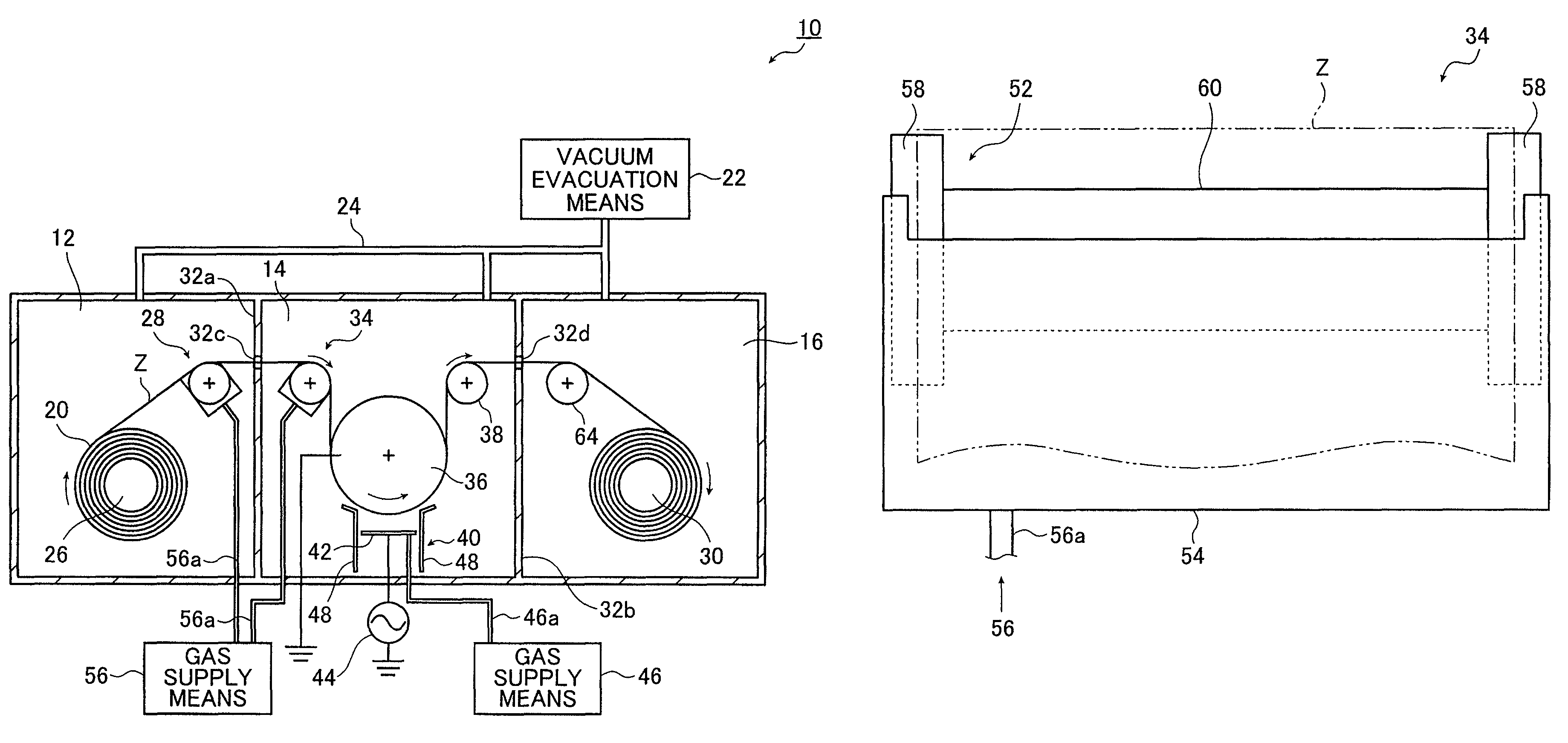
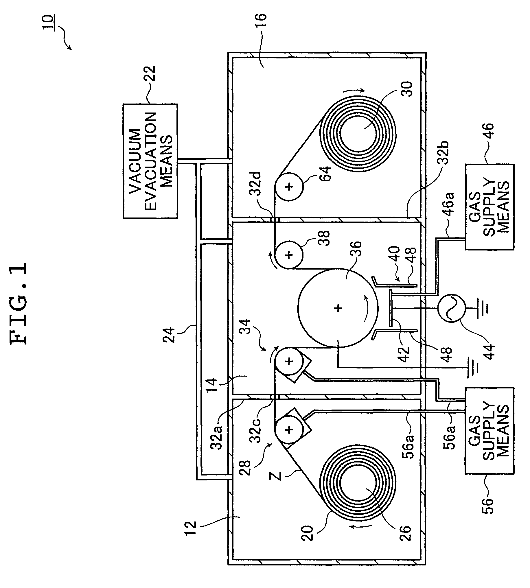
[0034]FIG. 1 schematically shows an embodiment of the vacuum deposition device of the present invention in which the sheet conveying unit of the present invention is used.

[0035]A vacuum deposition device (hereinafter referred to as the “deposition device”) 10 shown in FIG. 1 is a device in which a film (sheet-like subject) is formed on a substrate Z in the form of a long film strip (starting film material) by vacuum deposition (by capacitively coupled plasma-enhanced chemical vapor deposition (hereinafter abbreviated as “CCP-CVD”) in the illustrated embodiment). The deposition device 10 includes a feed chamber 12, a film deposition chamber 14 and a take-up chamber 16.

[0036]The deposition device 10 is a device in which a film is deposited by the so-called “roll-to-roll” system as describ...


PUM

PropertyMeasurementUnit
diameteraaaaaaaaaa
frictionaaaaaaaaaa
rotational speedaaaaaaaaaa

Abstract

The conveying unit conveys a long sheet-like subject in its longitudinal direction. The conveying unit includes a stepped roller which has large-diameter portions spaced apart from each other in a direction perpendicular to a direction of conveyance of the sheet-like subject and having a larger diameter than a remainder of the stepped roller being a small-diameter portion of the stepped roller, the large-diameter portions supporting and conveying the sheet-like subject, a closed space forming subunit between the small-diameter portion of the stepped roller and the sheet-like subject and a gas supply subunit for supplying a gas to the closed space. The vacuum deposition device forms a film on a surface of a long substrate by vacuum deposition. The vacuum deposition device includes a vacuum chamber, a conveying device which includes the conveying unit and a film forming unit.

Description

[0001]The entire contents of a literature cited in this specification are incorporated herein by reference.BACKGROUND OF THE INVENTION[0002]This invention relates to conveyance of a long sheet-like subject (hereinafter simply referred to as the “sheet”). More specifically, this invention relates to a conveying unit capable of reducing damage to a sheet due to friction or other defect and a vacuum deposition device employing such conveying means.[0003]Various functional films (functional sheets) including gas barrier films, protective films, and optical films such as optical filters and antireflection films are used in various devices including optical devices, display devices such as liquid crystal displays and organic EL displays, semiconductor devices, and thin film solar batteries.[0004]These functional films have been formed by film formation (thin film formation) through vacuum deposition techniques such as sputtering and plasma CVD.[0005]Continuous deposition of a film on a lo...

Claims


Application Information

Patent Timeline
Patent Type & Authority Patents(United States)
IPC IPC(8): C23C16/00C23C14/00
CPCB65H20/02B65H27/00B65H2301/5114B65H2406/11B65H2601/2532B65H2701/1719B65H2801/61
Inventor NAKAGAME, MASAMINISHIDA, HIROYUKITAKEUCHI, HIDEAKI
Owner FUJIFILM CORP
Why Eureka
Try Eureka