Spread illuminating apparatus

a technology of illumination apparatus and circuit board, which is applied in the direction of mechanical apparatus, lighting and heating apparatus, instruments, etc., can solve the problems of further complicated connection work without using connectors, and it is practically difficult to make circuit boards b>, so as to facilitate connection work between each of the circuit boards, improve the efficiency of light emitted from the light source and the light guiding plate

Active Publication Date: 2012-10-18
MINEBEAMITSUMI INC
View PDF2 Cites 5 Cited by
  • Summary
  • Abstract
  • Description
  • Claims
  • Application Information

AI Technical Summary

Benefits of technology

[0030]With the above structure, the connector is arranged on the mounting surface side of the circuit board on which the light source is mounted. Further, the length of the connector in its optical axis direction is made smaller than the length of the light source in its optical axis direction. Accordingly, with no interference from the connector, it is possible that the light source mounted on the circuit boards can be closely arranged relative to the side end face of the light guiding plate. Light incidence efficiency of the light emitted from the light source with respect to the light guiding plate can be improved. Still further, the region sandwiched between the side end face of the light guiding plate and the circuit board can be effectively used for a place in which the connector is arranged.
[0031]Since the present invention has the above structure, it is possible that the total size of the circuit board constituting the spread illuminating apparatus freely increases by connecting several small circuit boards. Connection works between each of the circuit boards can also be facilitated by applying the present invention.

Problems solved by technology

However, it is practically difficult to make the circuit board 104 large enough to correspond to the size of the light guiding plate 101 due to restriction factors such as an LED mounting apparatus or an available reflow size.
However, connection works without using the connector will be further complicated.

Method used


Image

  • Spread illuminating apparatus
  • Spread illuminating apparatus
  • Spread illuminating apparatus

Examples


Embodiment Construction

[0037]Hereinafter, some embodiments of the present invention will be described with reference to the attached drawings. In this case, the same or corresponding components with conventional arts will be denoted by the same reference numerals, and detail description thereto will be omitted.

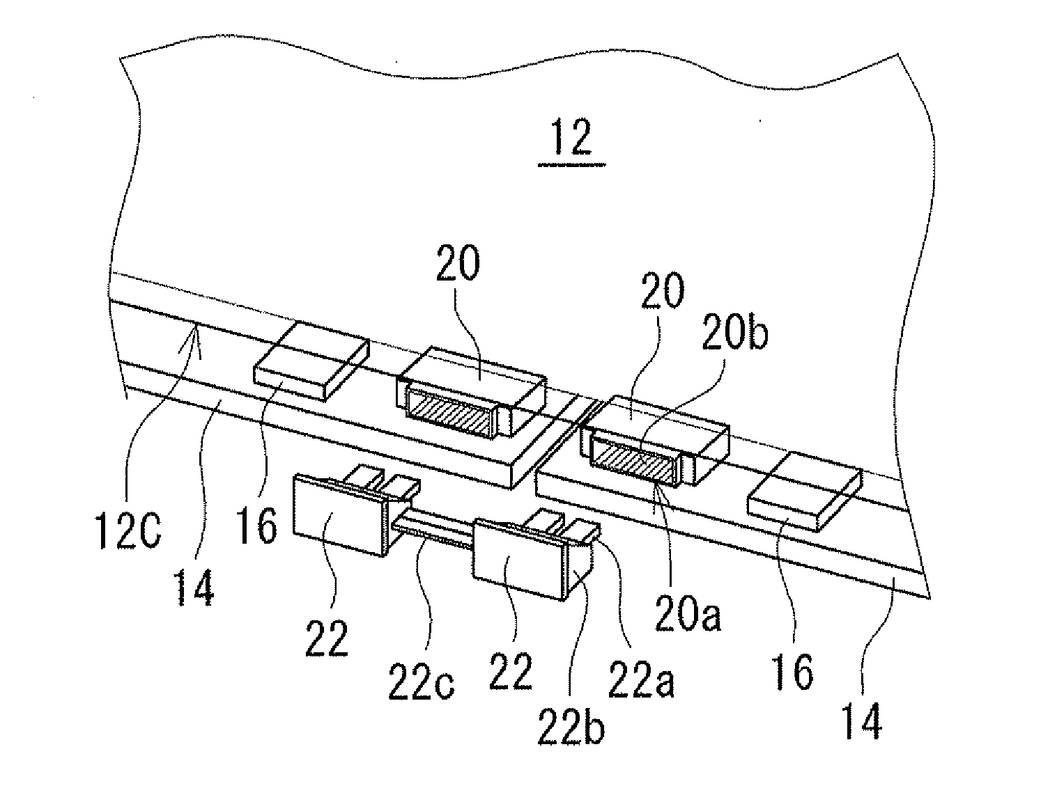
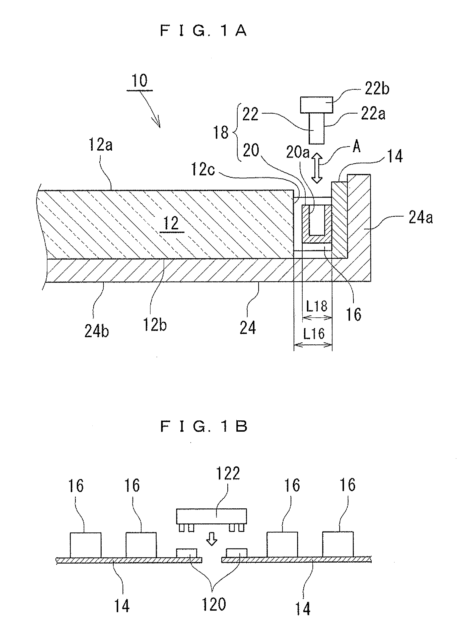
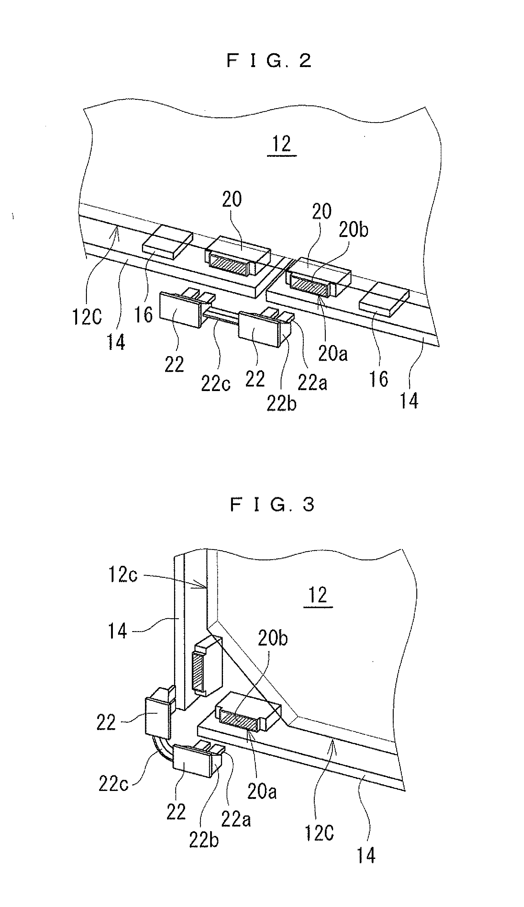
[0038]As illustrated in FIG. 1A, a spread illuminating apparatus 10 according to an embodiment of the present invention is the sidelight type spread illuminating apparatus that includes: a light guiding plate 12; a plurality of circuit boards 14 that are arranged along a longitudinal direction of a light incident surface 12c thereby facing the side end face (light incident surface) 12c of the light guiding plate 12; and a plurality of light sources (LEDs) 16 that are mounted on the circuit boards 14 and are arranged so as to face the light incident surface 12c of the light guiding plate 12. In addition, the spread illuminating apparatus 10 includes a connector 18 that electrically connects the adjac...


PUM


Abstract

A sidelight type spread illuminating apparatus includes a light guiding plate; a plurality of circuit boards arranged so as to face a side end face of the light guiding plate; a light source mounted on the circuit boards; and a connector that electrically connects the circuit boards adjacent to each other. The connector includes a socket and a plug that are removable therebetween. The socket and the plug are configured to be removable in a direction parallel to each mounting surface of the light sources of the circuit boards in a state that either the socket or the plug is fixed to ends of the circuit boards adjacent to each other.

Description

BACKGROUND OF THE INVENTION[0001]1. Field of the Invention[0002]The present invention relates to a spread illuminating apparatus.[0003]2. Description of the Related Art[0004]Along with the high performance of recent blue light-emitting diodes (LED), a spread illuminating apparatus, to which LEDs are applied as a light source, has been widely used not only for the backlight of a large flat-screen television but also for the lighting device of an indoor lighting.[0005]A generally known structure of the spread illuminating apparatus is a so-called sidelight type. This type includes a light guiding plate that forms a light emitting surface, LEDs that are arranged to face a side end face of the light guiding plate, and a circuit board on which the LEDs are mounted. FIG. 4 schematically illustrates this type of spread illuminating apparatus. The basic structure of a sidelight type spread illuminating apparatus 100 includes a light guiding plate 101, a plurality of LEDs 102 that are arrang...

Claims


Application Information

Patent Timeline
Patent Type & Authority Applications(United States)
IPC IPC(8): F21V8/00
CPCG02F1/133615G02B6/0083H05K1/14H05K2201/10287H05K2201/10106H05K2201/10189H05K1/148
Inventor OHNO, YASUONISHIO, MASAHISA
Owner MINEBEAMITSUMI INC
Why Eureka
Try Eureka