
Backlight assembly including a light source cover including a sidewall cover portion which contacts with an exterior surface of a sidewall of a receiving container and a light source cover portion which covers a light source and a portion of the exiting surface of a light guide plate, display device having the same and method of assembling the display device

a technology of backlight assembly and light source, which is applied in the direction of lighting and heating equipment, instruments, manufacturing tools, etc., can solve the problems of light loss and achieve the effect of increasing the efficiency of incident ligh

Active Publication Date: 2014-05-27
SAMSUNG DISPLAY CO LTD
View PDF15 Cites 0 Cited by
  • Summary
  • Abstract
  • Description
  • Claims
  • Application Information

AI Technical Summary

Benefits of technology

Example embodiments of the present invention provide a backlight assembly that prevents the lights from leaking, which increases the efficiency of the incident light. A light source cover covers the light source module and a portion of the light guide plate adjacent to the light source module. This prevents the lights from leaking between the light source module and the light guide plate.

Problems solved by technology

However, a gap may be generated between the upper surface of the light source and the mold frame, so that light may be leaked through the gap so that light loss may be generated.

Method used


Image

  • Backlight assembly including a light source cover including a sidewall cover portion which contacts with an exterior surface of a sidewall of a receiving container and a light source cover portion which covers a light source and a portion of the exiting surface of a light guide plate, display device having the same and method of assembling the display device
  • Backlight assembly including a light source cover including a sidewall cover portion which contacts with an exterior surface of a sidewall of a receiving container and a light source cover portion which covers a light source and a portion of the exiting surface of a light guide plate, display device having the same and method of assembling the display device
  • Backlight assembly including a light source cover including a sidewall cover portion which contacts with an exterior surface of a sidewall of a receiving container and a light source cover portion which covers a light source and a portion of the exiting surface of a light guide plate, display device having the same and method of assembling the display device

Examples


Embodiment Construction

[0036]Hereinafter, exemplary embodiments of the present invention will be explained in detail with reference to the accompanying drawings.

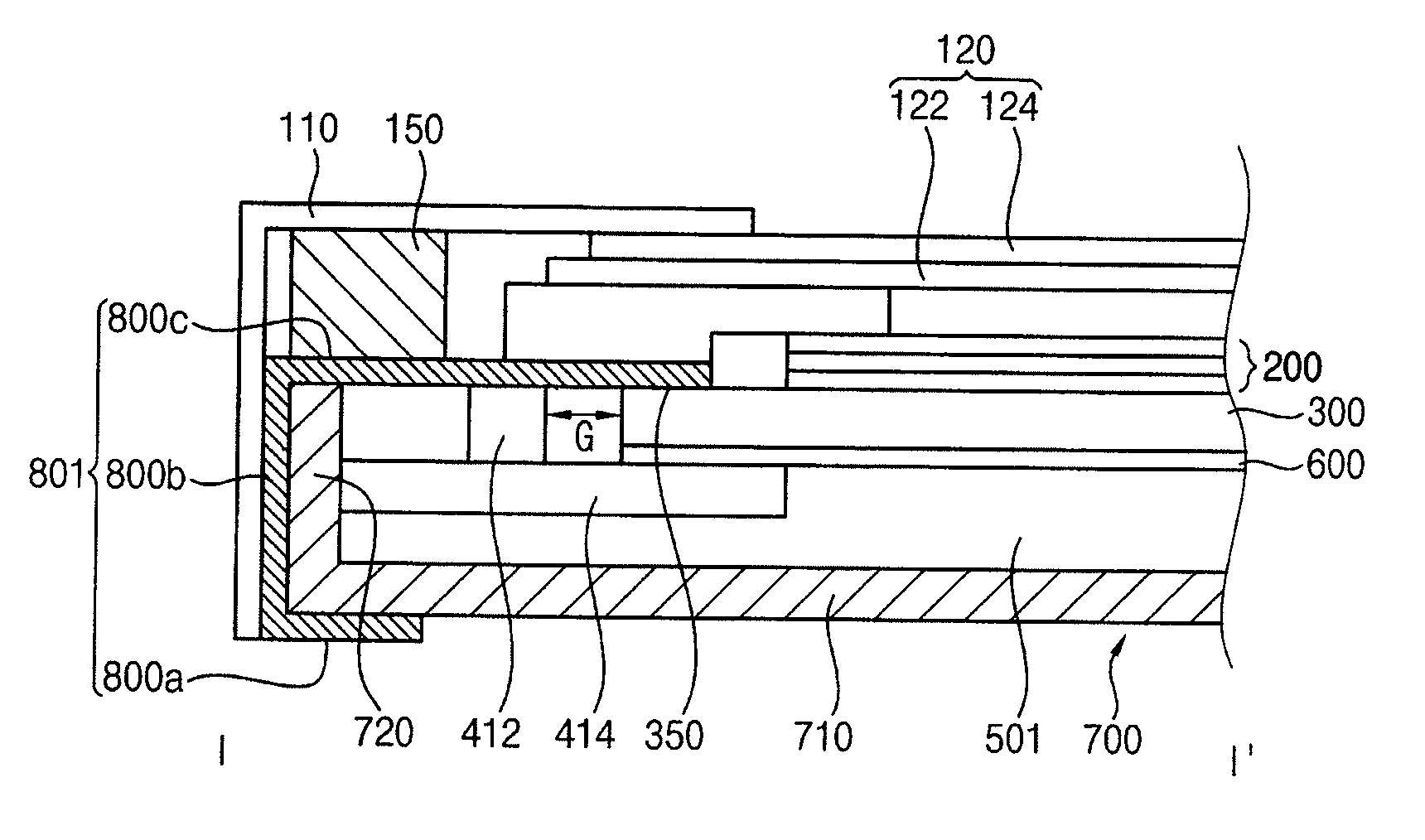
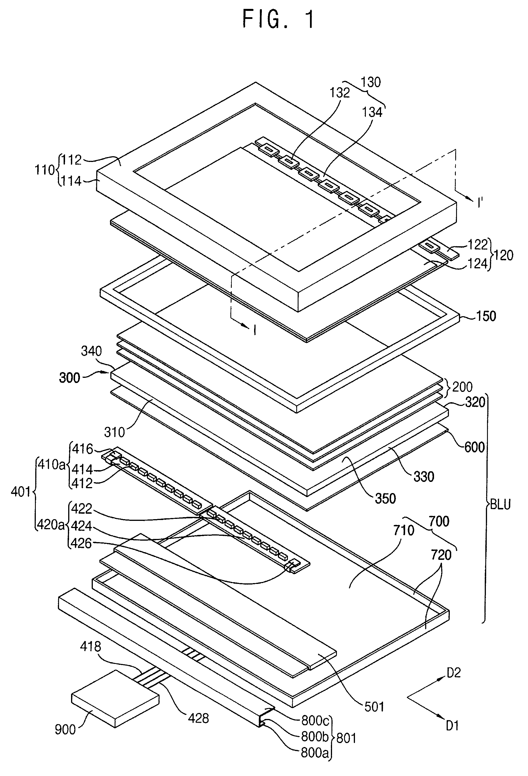
[0037]FIG. 1 is an exploded perspective view illustrating a display device according to an exemplary embodiment of the present invention. FIG. 2 is a cross-sectional view taken along a line I-I′ of FIG. 1.

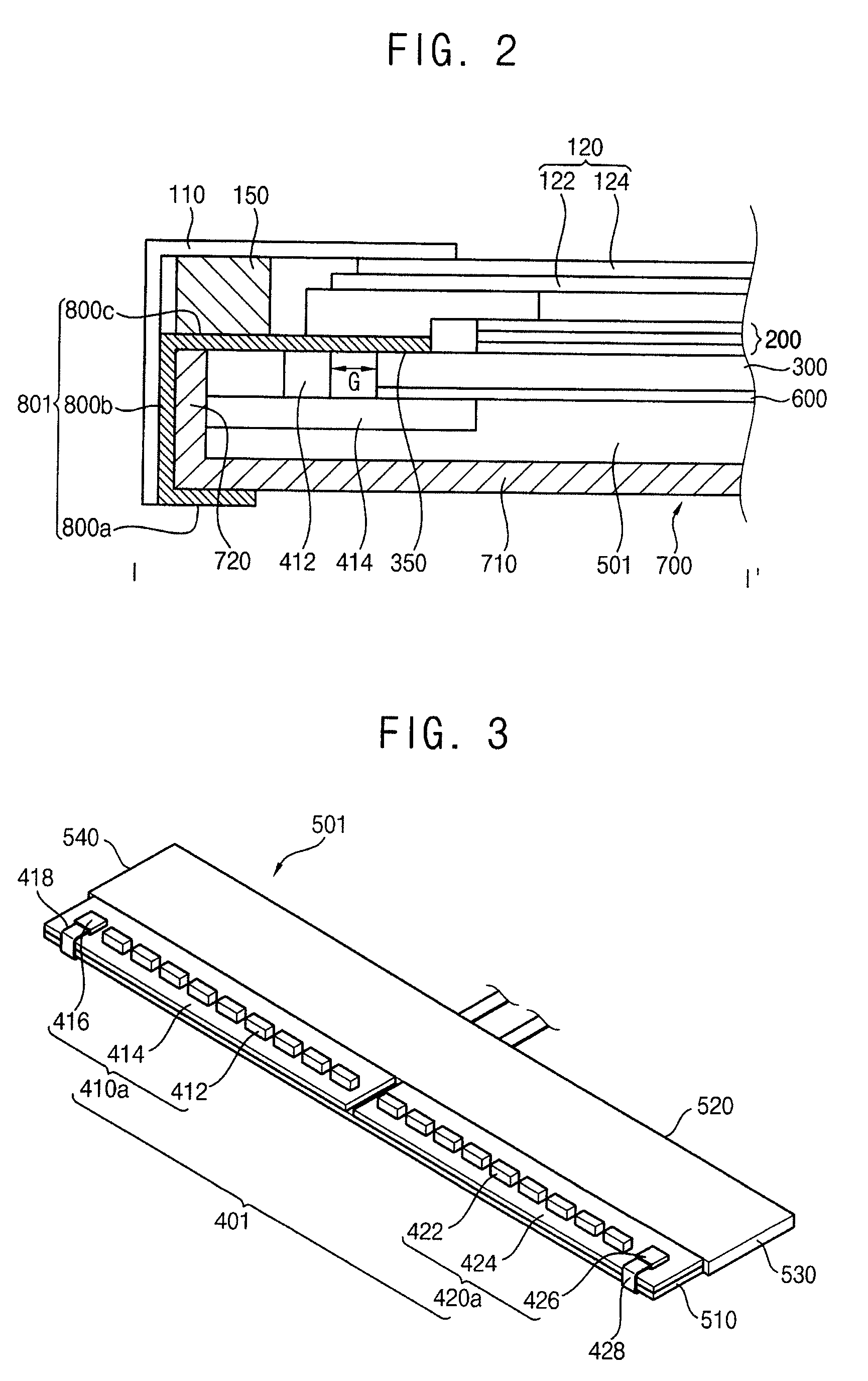
[0038]Referring to FIGS. 1 and 2, a display device according the present exemplary embodiment includes a top chassis 110, a display panel 120, a panel driving part 130, a mold frame 150 and a backlight assembly BLU.

[0039]The top chassis 110 is disposed on the display panel 120 to protect the display panel 120 from an external impact. The top chassis 110 includes a panel supporting part 112 which supports edge portions of the panel 120 and plural chassis sidewalls 114 extended from the edge portions of the panel supporting part 112. A window exposing a display area of the display panel 120 is formed through an upper surface of the top chassis 110....


PUM

PropertyMeasurementUnit
driving voltageaaaaaaaaaa
anisotropyaaaaaaaaaa
dielectric constantaaaaaaaaaa

Abstract

A backlight assembly includes a receiving container, a first light source module and a first light source cover. The receiving container includes a bottom portion, a first sidewall and a second sidewall connected to the bottom portion. The first light source module is supported by the bottom portion and adjacent to the first side wall. The first light source cover makes contact with an exterior surface of the first sidewall. The first light source cover surrounds the second sidewall so that a first end portion of the first light source cover covers the first light source module.

Description

CROSS-REFERENCE TO RELATED APPLICATION[0001]This application claims priority under 35 U.S.C. §119 to Korean Patent Application No. 2011-0013552, filed on Feb. 16, 2011, the disclosure of which is hereby incorporated by reference herein in its entirety.BACKGROUND OF THE INVENTION[0002]1. Technical Field[0003]Example embodiments of the present invention relate to a backlight assembly, a display device having the backlight assembly and a method of assembling the display device. More particularly, example embodiments of the present invention relate to a backlight assembly capable of preventing light leakage, a display device having the backlight assembly and a method of assembling the display device.[0004]2. Description of the Related Art[0005]A liquid crystal display (“LCD”) device may display an image using a liquid crystal that has optical characteristics such as, for example, anisotropy of refractivity and electrical characteristics such as anisotropy of dielectric constant. LCD dev...

Claims


Application Information

Patent Timeline
Patent Type & Authority Patents(United States)
IPC IPC(8): F21V15/01G09F13/04F21V29/00F21V29/503F21V29/70
CPCY10T29/49826G02F1/133308G02B6/0031G02F2001/133314G02B6/0091G02F2001/13332G02B6/0081G02F2001/133317G02F1/13332G02F1/133317G02F1/133314G02B6/0053G02F1/133524G02F1/133628
Inventor BAE, HYUN-CHULNOH, CHEOL-YONGCHOI, SEONG-SIK
Owner SAMSUNG DISPLAY CO LTD
Learn More