Self-closing device for sliding doors

a self-closing and sliding door technology, applied in the direction of wing openers, multi-purpose tools, constructions, etc., can solve the problems of no adjustment of the closing speed, unsafe situations, and type of devices, and achieve the effects of avoiding undesired noise and slum shutting, reducing and compacting size, and being convenient to us

Active Publication Date: 2012-11-15
KLEIN IBERICA
View PDF12 Cites 2 Cited by
  • Summary
  • Abstract
  • Description
  • Claims
  • Application Information

AI Technical Summary

Benefits of technology

[0002]The present invention refers to a self-closing device for sliding doors, of the type comprising at least one sliding leaf which is hung from an upper profile and which is configured to displace in the direction thereof. Where said device enables the sliding leaf to close autonomously, at a constant speed adjusted at the users will. The closing movement is performed in a secure, efficient, smooth and stable manner, avoiding undesired noises and slum shuts. The device of the present invention has in turn a reduced and compact size that facilitates mounting and maintenance tasks.

Problems solved by technology

This type of devices has several problems.
The first one of them is that, once the spring is selected and the device is installed there is no possibility of adjusting the closing speed.
The second problem is that the closing does not occur at constant speed, that is, the sliding leaf is initially accelerated and then slows down producing sudden movements which can produce clashes, dangerous situations and swinging movements which can produce vibrations.
The third problem is that, with time the spring starts to lose elastic strength until being insufficient to produce the complete closing of the door.
This type of devices has problems similar to the preceding case.
That is, there is no possibility of adjusting the closing speed, said closing does not occur at constant speed and also sudden acceleration and deceleration events occur that can deteriorate or break elements of the device or the door, or even cause accidents.
Besides these problems, there are mounting difficulties produced by the fact that there is an external stop to attain a correct adjustment.

Method used


Image

  • Self-closing device for sliding doors
  • Self-closing device for sliding doors
  • Self-closing device for sliding doors

Examples


Embodiment Construction

)

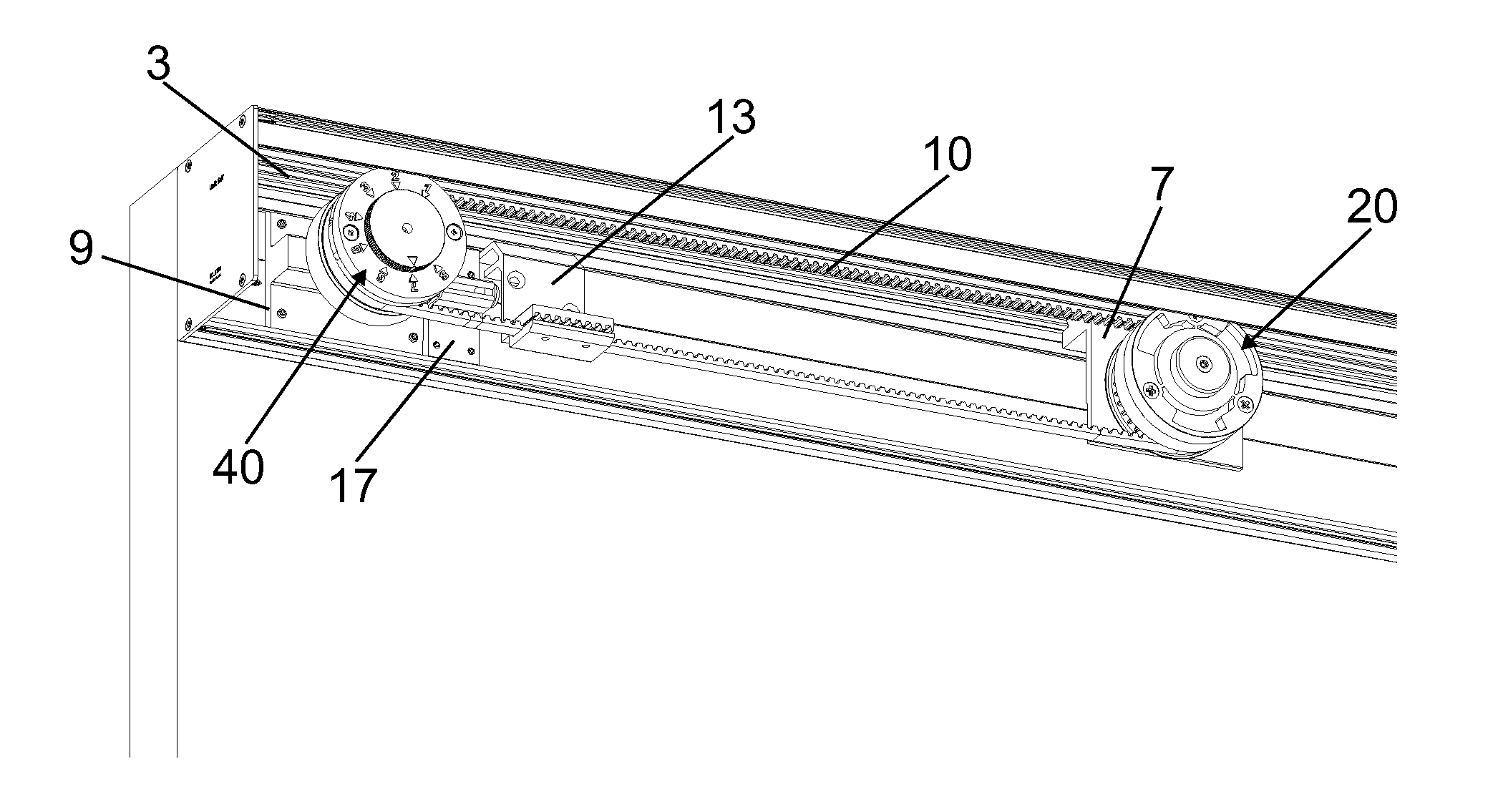
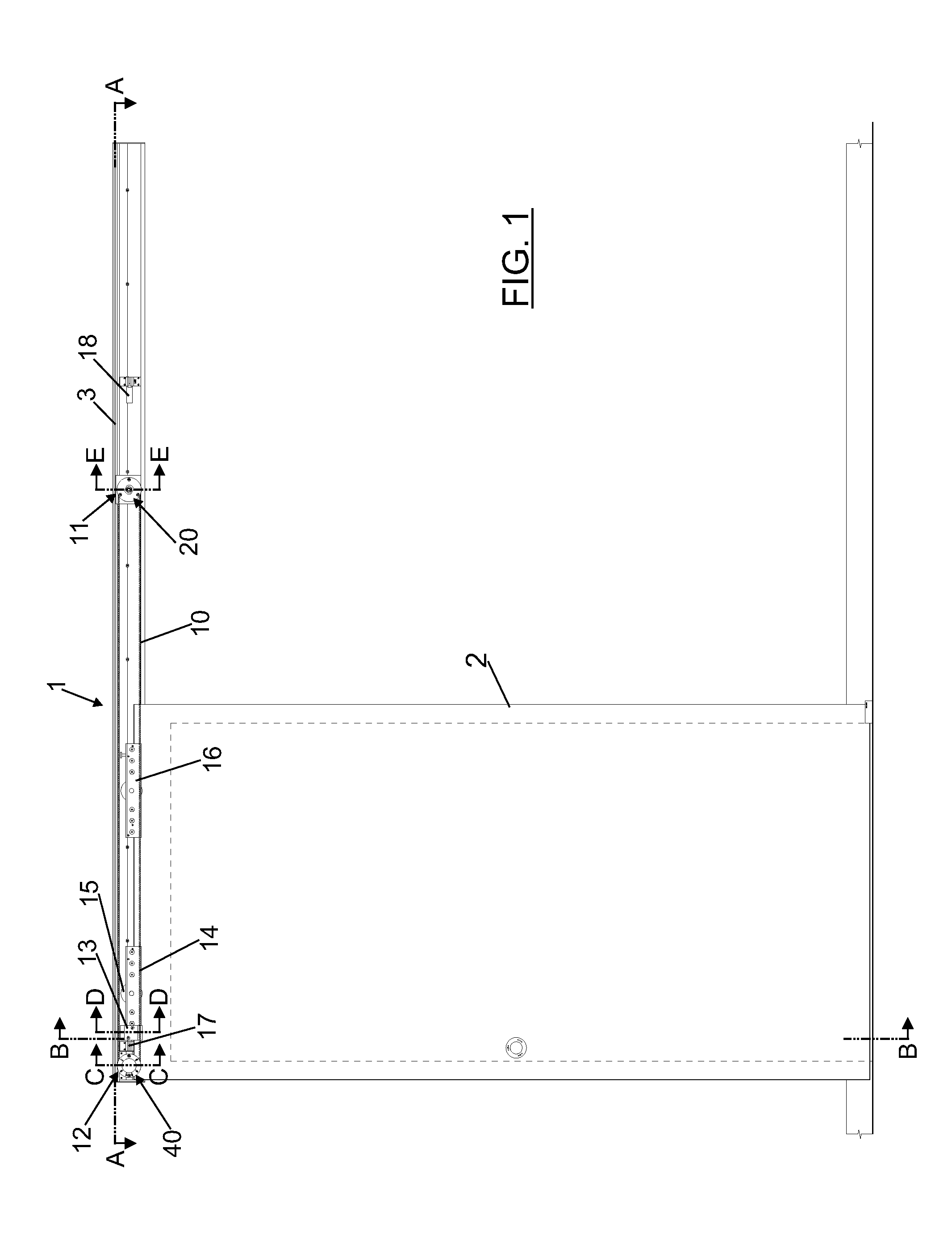
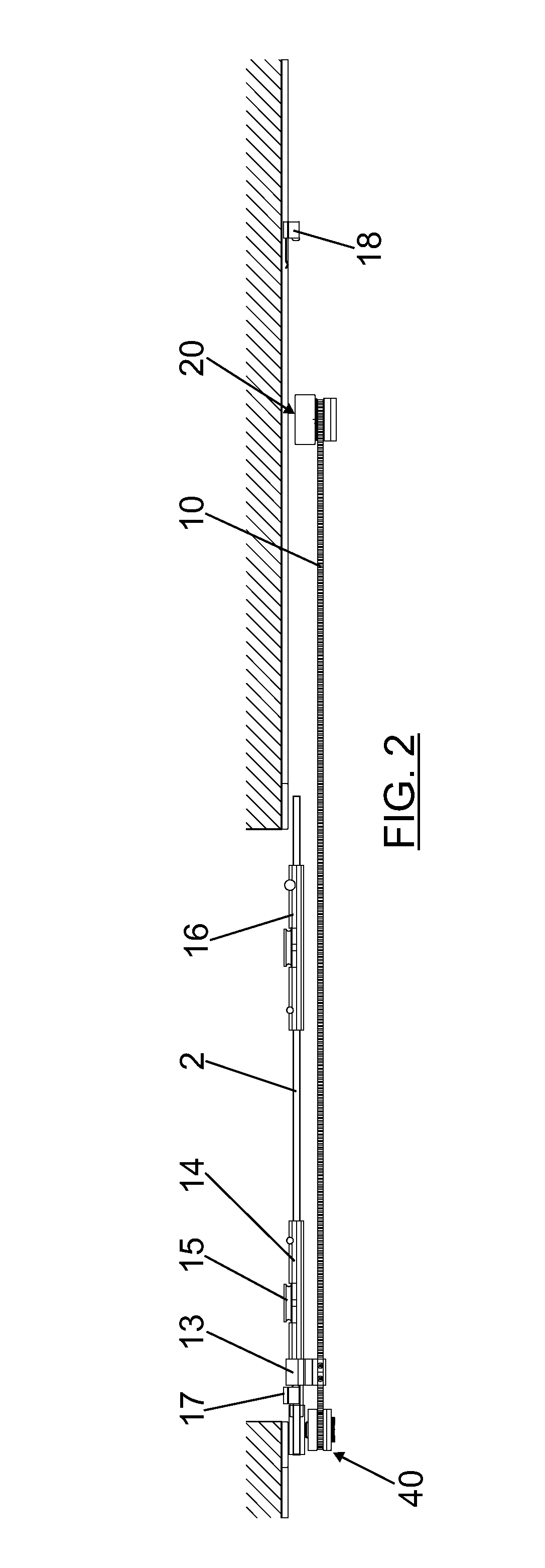
[0054]FIG. 1 shows an elevation view of the device (1) of the present invention applied to a sliding door comprising a sliding leaf (2) which is hung from an upper profile (3) and which is configured to displace in the direction thereof. The door is represented with the sliding leaf (2) in the closed position.

[0055]As it can be seen, the device (1) comprises:[0056]a drive belt (10) arranged along the upper profile (3) and configured to be joined to the sliding leaf (2);[0057]a closing pulley (20), provided with elastic means (30), that is arranged on a first rotation axis (4) integral to the upper profile (3), FIGS. 6 and 11, and that engages with a first end (11) of the drive belt (10), where said pulley (20) is configured to:[0058]load the elastic means (30) during the opening of the sliding leaf (2) through the rotation movement transmitted by the drive belt (10); and to[0059]push the sliding leaf (2) during the closing thereof through the rotation movement in the opposite direc...


PUM


Abstract

A self-closing device is for sliding doors of the type including at least one sliding leaf (2) which is hung from an upper profile (3). The device (1) includes a drive belt (10) configured to be joined to the sliding leaf (2); a closing pulley (20), provided with an elastic device (30), which is arranged on a first rotation axis (4) integral to the upper profile (3) and which engages with a first end (11) of the drive belt (10); and a brake pulley (40), provided with a stop (50), which is arranged on a second rotation axis (5) integral to the upper profile (3) and which engages with a second end (12) of the drive belt (10) opposite to the first end (11). The rotation movement of both pulleys (20, 40) is connected by the drive belt (10).

Description

[0001]This application claims benefit of U.S. Provisional Ser. No. 61 / 485,489, filed 12 May 2011 and which application is incorporated herein by reference. To the extent appropriate, a claim of priority is made to the above disclosed application.OBJECT OF THE INVENTION[0002]The present invention refers to a self-closing device for sliding doors, of the type comprising at least one sliding leaf which is hung from an upper profile and which is configured to displace in the direction thereof. Where said device enables the sliding leaf to close autonomously, at a constant speed adjusted at the users will. The closing movement is performed in a secure, efficient, smooth and stable manner, avoiding undesired noises and slum shuts. The device of the present invention has in turn a reduced and compact size that facilitates mounting and maintenance tasks.[0003]The present invention is especially suitable for its use in sliding doors which have sliding leaves manufactured using any type of ma...

Claims


Application Information

Patent Timeline
Patent Type & Authority Applications(United States)
IPC IPC(8): E05F11/54
CPCE05F1/16E05F11/54E05Y2201/48Y10T16/56Y10T16/568Y10T16/577Y10T16/287E05Y2201/652
Inventor TARREGA LLORET, MIGUEL ANGEL
Owner KLEIN IBERICA
Why Eureka
Try Eureka