Hoisting and tensioning bearing saver

a bearing saver and tensioning technology, applied in the field of sheave assemblies, can solve the problems of uneven and increased wear of the sheave bearing assembly

Active Publication Date: 2022-03-22
NAT OILWELL VARCO LP
View PDF121 Cites 0 Cited by
  • Summary
  • Abstract
  • Description
  • Claims
  • Application Information

AI Technical Summary

Benefits of technology

[0006]The present disclosure, in one embodiment, relates to a sheave assembly having a shaft and cone sub-assembly configured to rotate about a central axis. The sub-assembly may have a sheave shaft configured to be arranged at a center of one or more sheaves. The sub-assembly may further have one or more pairs of bearing cones arranged about the sheave shaft, each pair of bearing cones configured to interface with a plurality of bearing rollers. The shaft and cone sub-assembly may be configured to rotate about the central axis independent of the one or more sheaves. In some embodiments, the sheave assembly may have a spanner coupled to the shaft and cone sub-assembly and configured for rotating the sub-assembly about the central axis. Moreover, the sheave assembly may have one or more sheaves arranged about the shaft and cone sub-assembly, each sheave corresponding with a bearing cone. In some embodiments, a plurality of bearing rollers may be arranged between each sheave and its corresponding pair of bearing cones. In some embodiments, the shaft and cone sub-assembly may have an inner endcap coupled to an end of the sheave shaft and configured to hold the one or more pairs of bearing cones in a fixed position with respect to the sheave shaft. The sheave assembly may additionally have an outer endcap coupled to an end of the shaft and cone sub-assembly and configured to prevent undesired rotation of the shaft and cone sub-assembly during handling operations. The shaft and cone sub-assembly may, in some embodiments, have a plunger configured to engage with one or more corresponding openings or grooves to limit rotation of the shaft and cone sub-assembly. The plunger may be a ratcheting plunger that allows one-directional rotation of the shaft and cone sub-assembly.
[0008]The present disclosure, in another embodiment, relates to a method of extending the life of one or more bearing cones arranged in a sheave assembly. The method may include arranging a shaft and cone sub-assembly of the sheave assembly through one or more sheaves and in a first rotational position about a central axis of rotation. The method may additionally include assessing an amount of wear on the one or more bearing cones, and rotating the shaft and cone sub-assembly about the central axis of rotation, without rotating the one or more sheaves, to a second rotational position. In some embodiments, rotating the shaft and cone sub-assembly may include rotating the sub-assembly approximately 90 degrees. In some embodiments, the method may include reserving a final rotational position in case of failure. Rotating the shaft and cone sub-assembly may additionally include decoupling an outer endcap from the shaft and cone sub-assembly, and pushing or pulling a spanner coupled to the shaft and cone sub-assembly.

Problems solved by technology

Over time, a sheave bearing assembly may wear from load forces on the sheave.
In some cases, due to application of loading on the sheave, a sheave bearing assembly may wear at an uneven rate, such that some bearing rollers, cones, and / or cups, or portions thereof, within the bearing assembly may experience more wear than others.
As a portion of the bearing assembly becomes worn, sheaves may begin to wobble or rotate unevenly or with increased friction, which may affect lifting and / or tensioning operations or lead to safety concerns.

Method used


Image

  • Hoisting and tensioning bearing saver
  • Hoisting and tensioning bearing saver
  • Hoisting and tensioning bearing saver

Examples


Embodiment Construction

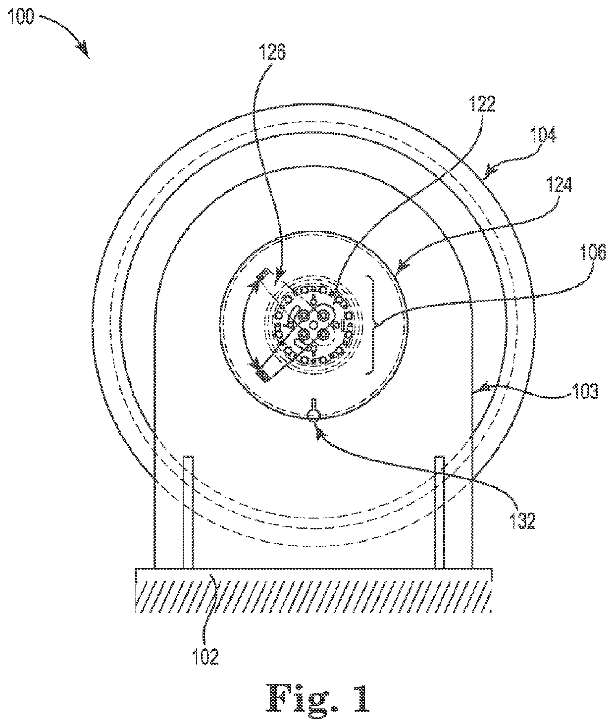
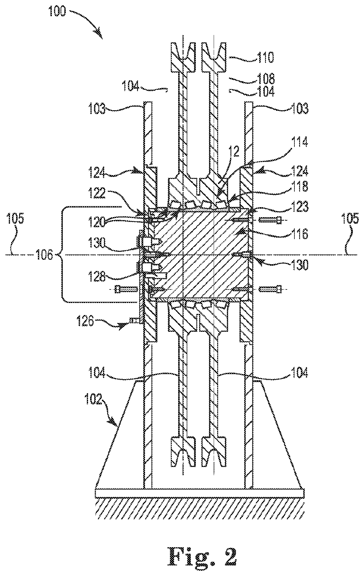
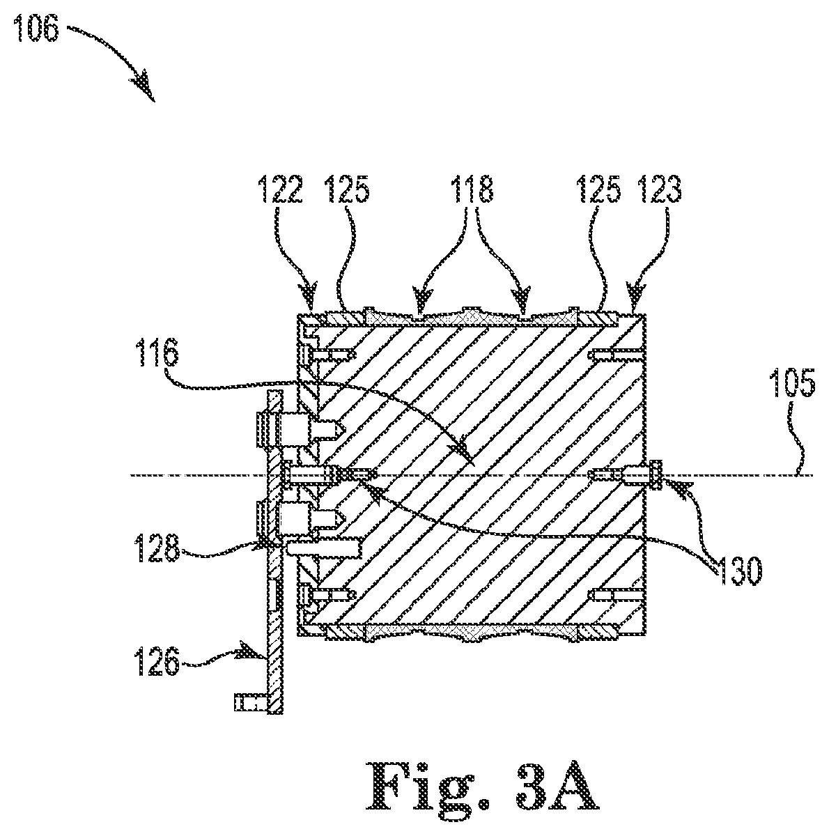
[0027]The present disclosure relates to a novel and advantageous devices, systems, and methods for extending the life of bearing systems within a sheave assembly by rotating bearing cones in the sheave assembly, so as to reposition the cones with respect to loading from handling operations. In particular, the present disclosure relates to a sheave assembly for use in a handling system, the sheave assembly having one or more sheaves arranged about a shaft and cone sub-assembly. The shaft and cone sub-assembly may include one or more bearing cones configured to interface with a plurality of bearing rollers to facilitate rotation of the one or more sheaves about the shaft and cone sub-assembly. The shaft and cone sub-assembly may be configured to be arranged in a fixed rotational position during handling operations. The shaft and cone sub-assembly may further be configured to be rotated or repositioned about a central, longitudinal axis of the sub-assembly. The shaft and cone sub-assem...


PUM


Abstract

A sheave assembly for use in a handling system or tensioning system, the sheave assembly having one or more sheaves arranged about a shaft and cone sub-assembly. The shaft and cone sub-assembly may include one or more pairs of bearing cones configured to interface with a plurality of bearing rollers to facilitate rotation of the one or more sheaves about the shaft and cone sub-assembly. The shaft and cone sub-assembly may be configured to be arranged in a fixed rotational position during handling or tensioning operations. The shaft and cone sub-assembly may further be configured to be rotated or repositioned about a central, longitudinal axis of the sub-assembly. The shaft and cone sub-assembly may be configured to rotate independent of the sheave(s) so as to reposition the one or more pairs of cones with respect to applied loading on the sheave assembly from the handling or tensioning operations.

Description

FIELD OF THE INVENTION[0001]The present disclosure relates to sheave assemblies for use in handling or tensioning lines, ropes, cables, or other flexible elongate tensile elements. Particularly, the present disclosure relates to devices, systems, and methods for extending the life of sheave bearing systems. More particularly, the present disclosure relates to devices, systems, and methods for rotating bearing cones in a sheave assembly, so as to reposition the cones with respect to loading from handling or tensioning operations.BACKGROUND OF THE INVENTION[0002]The background description provided herein is for the purpose of generally presenting the context of the disclosure. Work of the presently named inventors, to the extent it is described in this background section, as well as aspects of the description that may not otherwise qualify as prior art at the time of filing, are neither expressly nor impliedly admitted as prior art against the present disclosure.[0003]Lifting assembli...

Claims


Application Information

Patent Timeline
Patent Type & Authority Patents(United States)
IPC IPC(8): B66D3/00B66D3/06E21B19/00B66D3/08F16C19/54F16C25/06F16H55/36
CPCB66D3/08E21B19/00E21B19/006F16C19/541F16C25/06F16H55/36B66D2700/028
Inventor KAYBIDGE, REECE WILLIAM
Owner NAT OILWELL VARCO LP
Why Eureka
Try Eureka