Facet mirror device

a mirror device and facet technology, applied in the field of facet mirror devices, can solve the problems of frictional relative motion between the facet element and the support element, undesired imaging, introduction of etc., and achieve the effect of avoiding undesired parasitic forces and moments

Active Publication Date: 2016-10-11
CARL ZEISS SMT GMBH
View PDF20 Cites 1 Cited by
  • Summary
  • Abstract
  • Description
  • Claims
  • Application Information

AI Technical Summary

Benefits of technology

[0011]It is thus an object of the invention to, at least to some extent, overcome the above disadvantages and to allow well defined adjustment of the facet element to the desired position and orientation with respect to the support element while at least largely avoiding undesired parasitic forces and moments, respectively, in particular caused by frictional or resetting forces and moments, respectively.
[0012]This and other objects are achieved according to the invention which, on the one hand, is based on the teaching that it is possible to provide a simple and reliable, easily adjustable support to the facet element at least largely avoiding undesired parasitic forces and moments, respectively, if a clamping arrangement is used wherein a counter unit is introduced via which the free end of the tensioning element is supported on the support unit and which is arranged such that an axis of rotation of the counter unit with respect to the support device is defined which is located at least close to an axis of rotation of the facet element with respect to the support device.
[0013]This configuration has the advantage that (depending on the distance between the axis of rotation of the counter unit and the axis of rotation of the facet element) the counter unit may follow the rotation of the facet element such that bending of the tensioning element and, eventually, lateral deflection of a spring device is at least largely avoided, thereby at least largely avoiding introduction of undesired parasitic forces and moments, respectively, into the facet element.
[0014]It will be appreciated that such a configuration may be designed such that it allows at least largely frictionless relative adjustment motion of the clamping partners by temporarily relieving the clamping partners from the clamping force, e.g. using a pressurized fluid.
[0018]According to a third aspect of the invention there is provided a facet mirror device comprising a facet element, a support device and a clamping device. The facet element comprises a first support section, while the support device comprises a second support section contacting the first support section to support the facet element. The clamping device comprises a tensioning element, a first end of the tensioning element being connected to the facet element, a second end of the tensioning element being connected to a counter unit. The counter unit comprises a third support section, the support device comprising a fourth support section contacting the third support section to support the counter unit. The tensioning element, in a clamping state, is under tensile stress such that the first support section and the second support section are pressed against each other and the third support section and the fourth support section are pressed against each other to clamp the facet element in at least one of a given position and a given orientation. At least one of the second support section and the fourth support section defines an axis of rotation of the facet element, at least one of the second support section and the fourth support section further allowing substantially frictionless rotation of the facet element about the axis of rotation. The axis of rotation, in particular, is located at least close to an optical surface of the facet element.

Problems solved by technology

A particular problem in this context is proper heat removal from the optical components to avoid uneven thermal expansion of these components leading to uneven deformation of these components and, ultimately, to undesired imaging errors
This configuration, however, has the disadvantage that an adjustment of the orientation of the optical surface of the facet element by tilting the manipulating lever typically leads to a frictional relative motion between the facet element and the support element.
This frictional relative motion leads to the introduction of undesired parasitic forces and moments, respectively, into the facet element.
), however, has the disadvantage that, depending on the degree of rotation about the center of rotation defined by the spherical rear surface, either one of the end of the spring device contacting the manipulating lever and the manipulating lever is laterally deflected.
This results in undesired parasitic moments introduced into the facet element via the manipulating lever.

Method used


Image

  • Facet mirror device
  • Facet mirror device
  • Facet mirror device

Examples


first embodiment

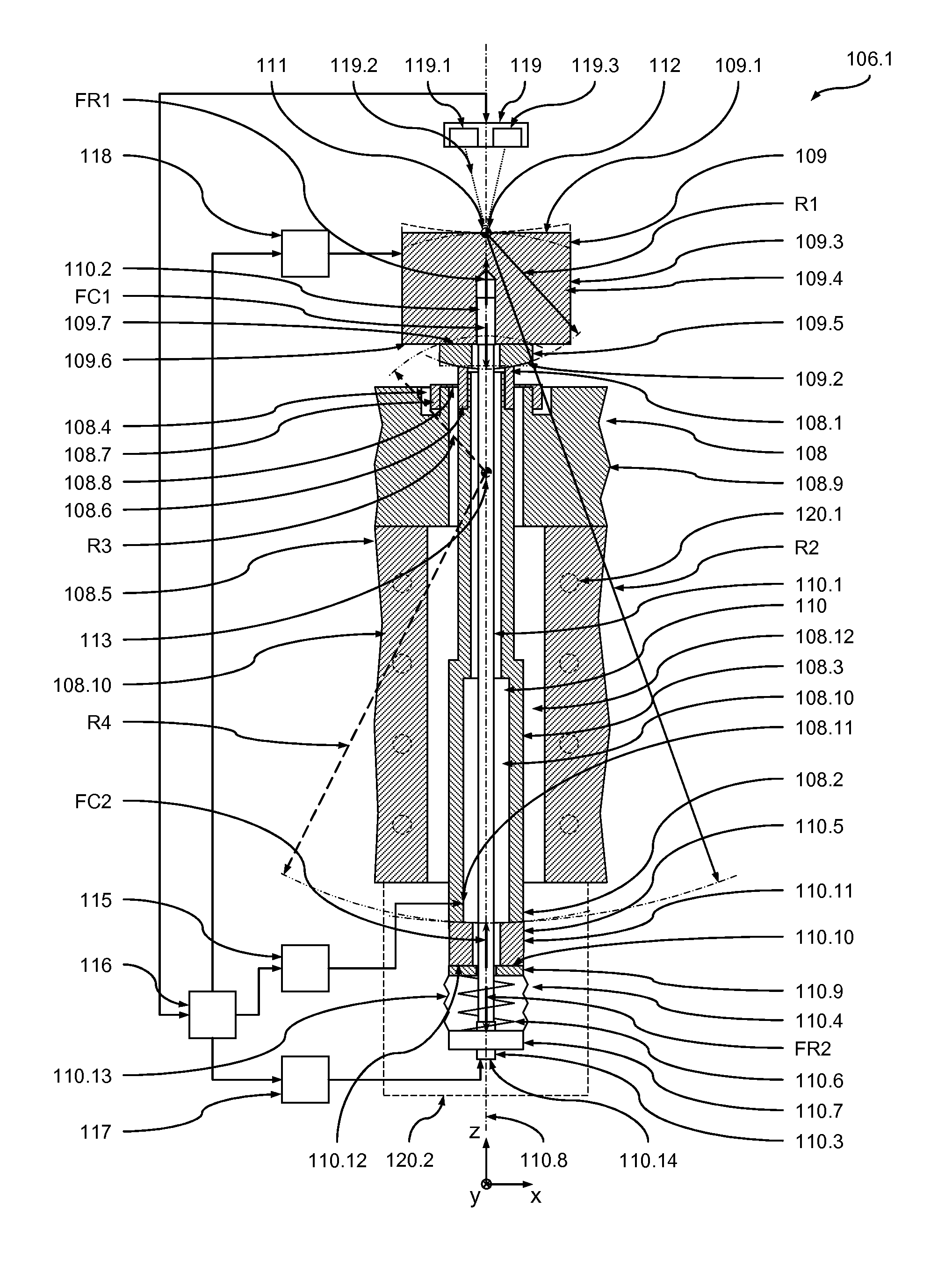
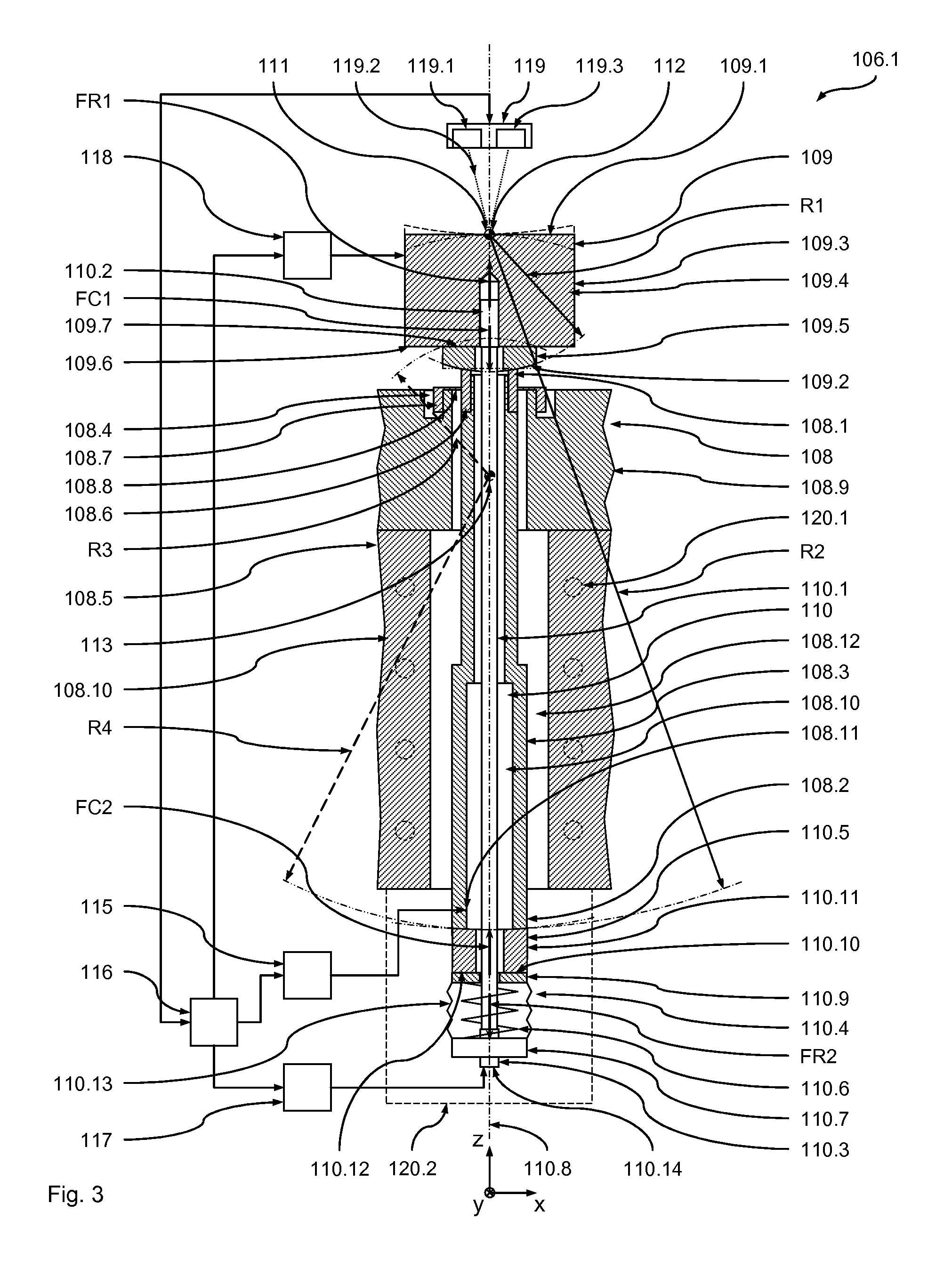
[0026]In the following, a first preferred embodiment of an optical imaging arrangement 101 according to the invention will be described with reference to FIGS. 1 to 10. In order to facilitate the explanations given below an xyz-coordinate system has been introduced into the Figures and will be used throughout the following description. In the following, the z-direction designates the vertical direction (i.e. the direction of the gravitational force). However, it will be appreciated that, with other embodiments of the invention, any other orientation in space of this xyz-coordinate system and the components of the optical imaging arrangement, respectively, may be chosen.

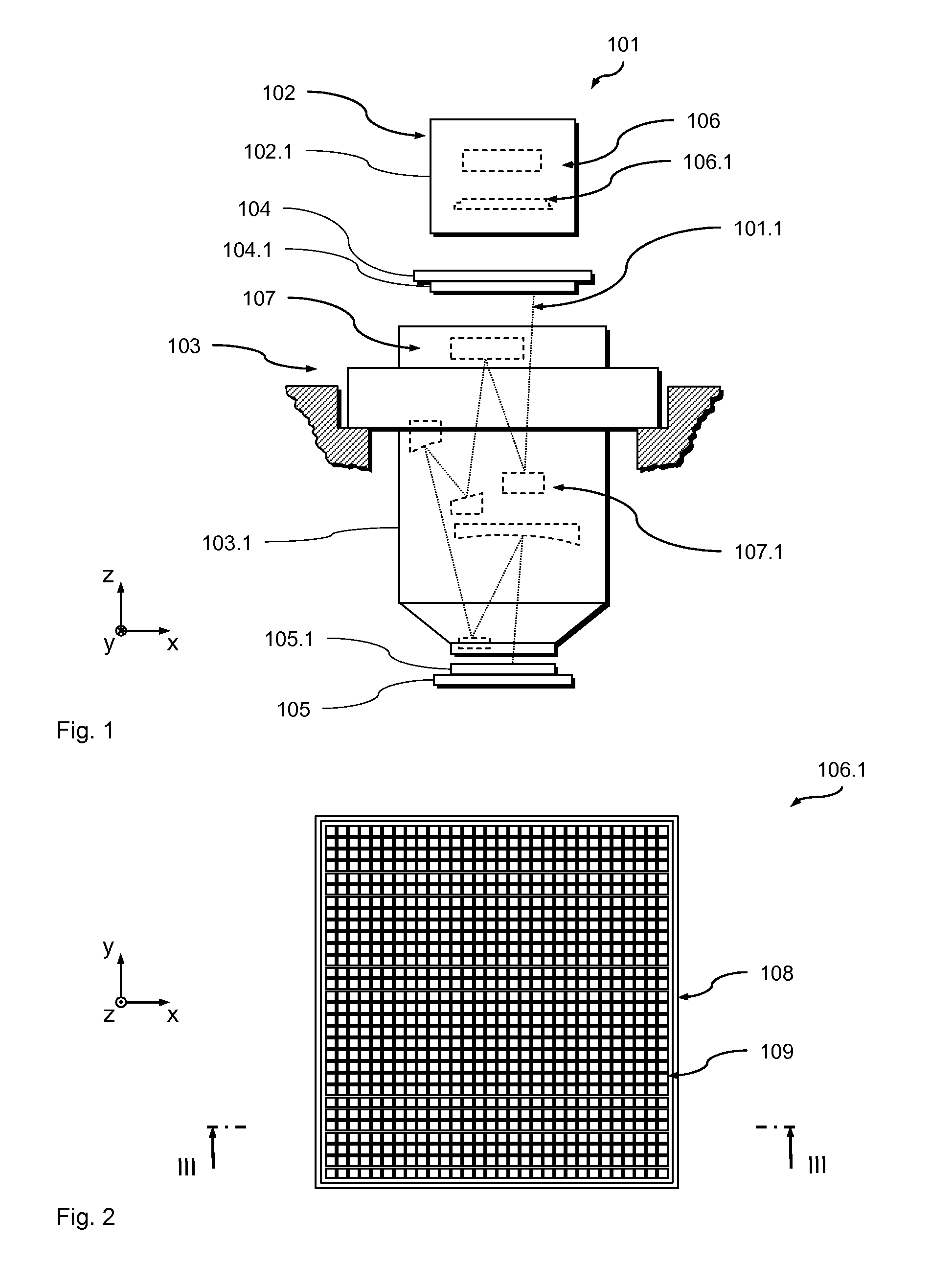
[0027]FIG. 1 is a schematic and not-to-scale representation of the optical imaging arrangement in the form of an optical exposure apparatus 101 used in a microlithography process during manufacture of semiconductor devices. The optical exposure apparatus 101 comprises an illumination unit 102 and an optical projection...

second embodiment

[0112]In the following, a second embodiment of the facet mirror device 206.1 according to the invention will be described with reference to FIGS. 1, 2, 4 and 5. The facet mirror device 206.1 in its basic design and functionality largely corresponds to the facet mirror device 106.1 and may replace the facet mirror device 106.1 in the optical imaging device 101 of FIG. 1. In particular, the method of supporting a facet element as they have been described above in relation to the first embodiment (FIG. 4) may be executed as well in the context of this facet mirror device 206.1. Thus, it is here mainly referred to the explanations given above and only the differences with respect to the facet mirror device 106.1 will be explained in further detail. In particular, similar parts are given the same reference numeral raised by the amount 100 and (unless explicitly described in the following) in respect to these parts reference is made to the explanations given above in the context of the fi...


PUM

PropertyMeasurementUnit
wavelengthaaaaaaaaaa
temperaturesaaaaaaaaaa

Abstract

A facet mirror device includes a facet element, a support device and a clamping device. The facet element includes a first support section, while the support device comprises a second support section contacting the first support section to support the facet element. The clamping device includes a tensioning element, a first end of the tensioning element being connected to the facet element a second end of the tensioning element being connected to a counter unit. The counter unit includes a third support section, the support device including a fourth support section contacting the third support section to support the counter unit.

Description

BACKGROUND OF THE INVENTION[0001]The invention relates to a facet mirror device that may be used within an optical device used in exposure processes, in particular in microlithography systems. It further relates to an optical imaging arrangement comprising such a facet mirror device. It further relates to a method of supporting a facet element of a facet mirror device. The invention may be used in the context of photolithography processes for fabricating microelectronic devices, in particular semiconductor devices, or in the context of fabricating devices, such as masks or reticles, used during such photolithography processes.[0002]Typically, the optical systems used in the context of fabricating microelectronic devices such as semiconductor devices comprise a plurality of optical element modules comprising optical elements, such as lenses, mirrors, gratings etc., in the light path of the optical system. Those optical elements usually cooperate in an exposure process to illuminate a...

Claims


Application Information

Patent Timeline
Patent Type & Authority Patents(United States)
IPC IPC(8): G03B27/54G02B7/182G03F7/20G02B26/08
CPCG02B7/1821G03F7/70116G02B26/0816G03F7/70075G02B7/1822
Inventor VOGT, MARTINHARTJES, JOACHIM
Owner CARL ZEISS SMT GMBH
Why Eureka
Try Eureka