Sub-membrane keycap indicator

a keycap indicator and sub-membrane technology, applied in contact mechanisms, instruments, computing, etc., can solve the problems of increasing the cost of type of keyboard, dim indicators, insufficient space under such a notebook keycap for placement, etc., to reduce or substantially eliminate unwanted light bleed, the effect of reducing or substantially eliminating light bleed

Active Publication Date: 2012-11-29
DELL PROD LP
View PDF6 Cites 71 Cited by
  • Summary
  • Abstract
  • Description
  • Claims
  • Application Information

AI Technical Summary

Benefits of technology

[0011]In one embodiment, an indicator light element may be positioned to direct a status-indicating light upward from beneath the switch membrane circuit to a light transmitting feature in the form of a lightguide molded into a keycap. This status-indicating light may be so directed upward in a pattern (e.g., narrow or contained light cone pattern) that is sufficiently narrow or contained within the periphery of the overlying keycap so as to reduce or substantially eliminate unwanted light bleed in the space between the keycap and the baseplate outwardly past the periphery of the overlying keycap that contains the indicator lightguide, e.g., so as to allow placement and illumination of a status-indicating aperture or lightguide off-center and near the periphery of the keycap. In a further embodiment, a mask may be optionally provided over the indicator light element in a position above the switch membrane circuit to further narrow the upwardly emitted light pattern, e.g., to allow closer placement to the periphery of a keycap without causing light bleed outwardly past the periphery of the overlying keycap that contains the indicator lightguide. Such a mask may be formed, for example, by utilizing membrane printing to mask around and above the indicator light element. In another exemplary embodiment, the disclosed devices and methods may be implemented to reduce or substantially eliminate light bleed outward from around the periphery of an indicator keycap without requiring additional masking parts (such as a Mylar sheet placed above the membrane material) or the presence of a flexible illumination guide.

Problems solved by technology

There is insufficient room under such a notebook keycap for placement of a traditional light guide or light mask that is typically utilized in a desktop keyboard assembly.
Current masking techniques require additional hand placed Mylar sections, extra cost, and are inconsistent causing LED's to be obscured and resulting in dim indicators.
Light bleed is less of a problem for frame (Chiclet) keyboards due to the shielding they provide, but this type of keyboard also increases cost.
This method may cause the key to feel stiffer than other similar sizes keys.

Method used


Image

  • Sub-membrane keycap indicator
  • Sub-membrane keycap indicator
  • Sub-membrane keycap indicator

Examples


Embodiment Construction

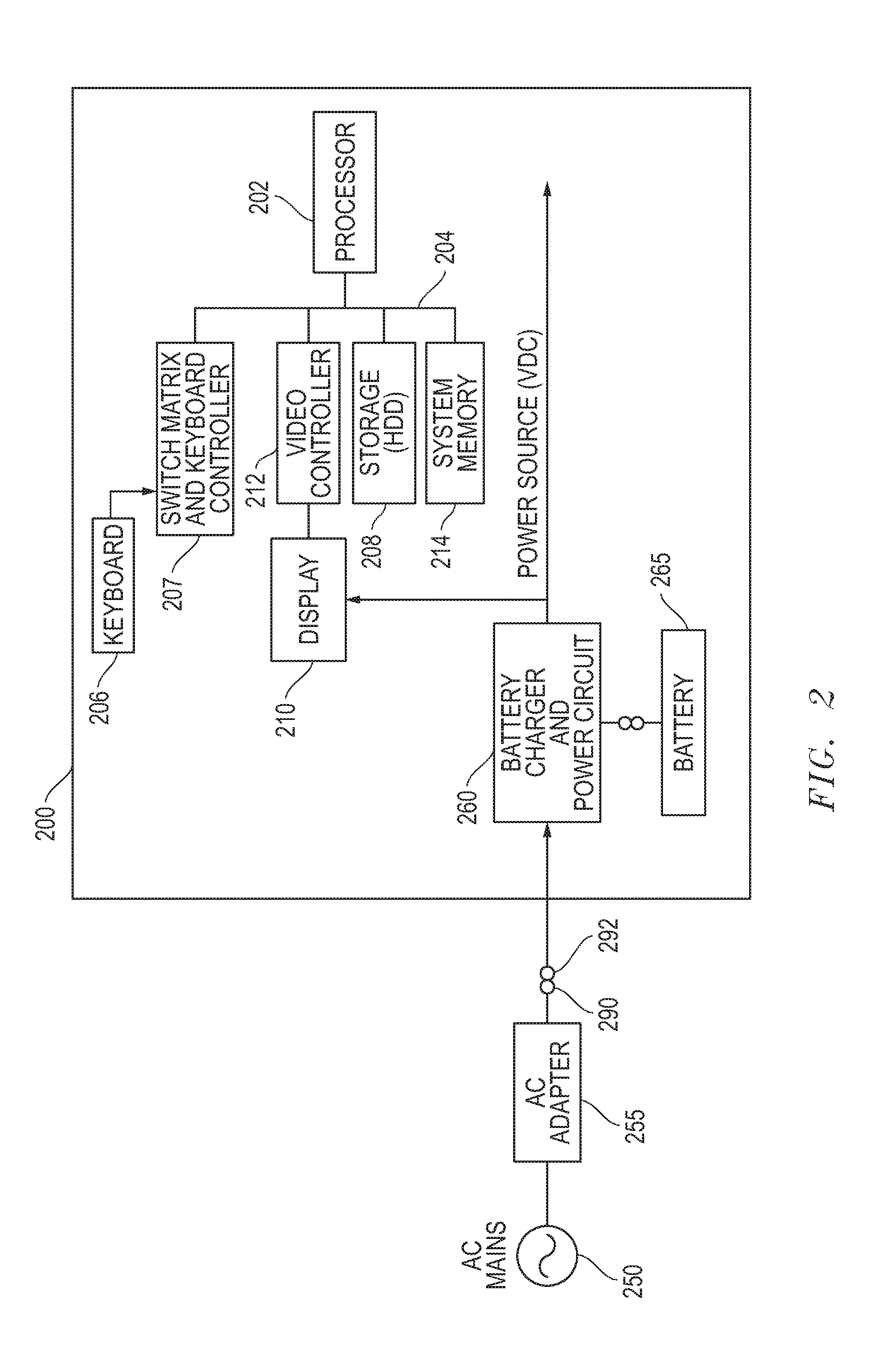
[0023]For purposes of this disclosure, an information handling system may include any instrumentality or aggregate of instrumentalities operable to compute, classify, process, transmit, receive, retrieve, originate, switch, store, display, manifest, detect, record, reproduce, handle, or utilize any form of information, intelligence, or data for business, scientific, control, or other purposes. For example, an information handling system may be a personal computer, a server computer system, a network storage device, or any other suitable device and may vary in size, shape, performance, functionality, and price. The information handling system may include random access memory (RAM), one or more processing resources such as a central processing unit (CPU) or hardware or software control logic, ROM, and / or other types of nonvolatile memory. Additional components of the information handling system may include one or more disk drives, one or more network ports for communicating with exter...


PUM


Abstract

Sub-membrane keycap indicators for keyboard assemblies may be implemented by positioning an indicator light element beneath a switch membrane circuit and within the baseplate of a key device. The indicator light element may be so positioned to direct light upward in a substantially narrow cone to an aperture or lightguide molded into a keycap in order to illuminate or light the indicator aperture or lightguide to indicate the current status of at least one component of an information handling system.

Description

FIELD OF THE INVENTION[0001]This invention relates generally to information handling systems and, more particularly, to keycap indicators for information handling systems.BACKGROUND OF THE INVENTION[0002]As the value and use of information continues to increase, individuals and businesses seek additional ways to process and store information. One option available to users is information handling systems. An information handling system generally processes, compiles, stores, and / or communicates information or data for business, personal, or other purposes thereby allowing users to take advantage of the value of the information. Because technology and information handling needs and requirements vary between different users or applications, information handling systems may also vary regarding what information is handled, how the information is handled, how much information is processed, stored, or communicated, and how quickly and efficiently the information may be processed, stored, or...

Claims


Application Information

Patent Timeline
Patent Type & Authority Applications(United States)
IPC IPC(8): H01H13/14
CPCG06F1/1662H01H13/023H01H2219/016H01H3/125H01H13/83
Inventor OZIAS, ORIN M.NERHOOD, II, ROBERT C.
Owner DELL PROD LP
Why Eureka
Try Eureka