Optical modulator and optical modulation method

a technology of optical modulator and optical modulator, applied in optics, instruments, electromagnetic transmission, etc., can solve problems such as conventional semiconductor mach-zehnder modulators

Active Publication Date: 2012-12-13
MITSUBISHI ELECTRIC CORP
View PDF4 Cites 14 Cited by
  • Summary
  • Abstract
  • Description
  • Claims
  • Application Information

AI Technical Summary

Benefits of technology

[0060]According to the present invention, it is possible to make the intensity of output light constant irrespectively of the value of a code during phase modulation.

Problems solved by technology

However, the conventional semiconductor Mach-Zehnder modulator described above has the following problems.

Method used


Image

  • Optical modulator and optical modulation method
  • Optical modulator and optical modulation method
  • Optical modulator and optical modulation method

Examples


Embodiment Construction

[0027]Exemplary embodiments of an optical modulator and an optical modulation method according to the present invention will be explained below in detail with reference to the accompanying drawings. The present invention is not limited to the embodiments.

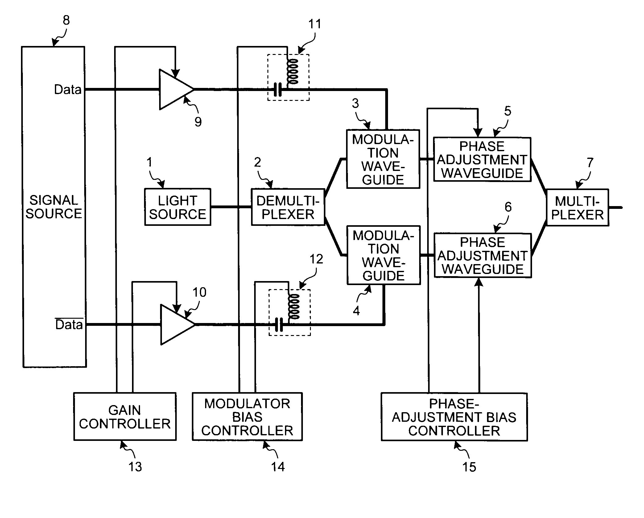
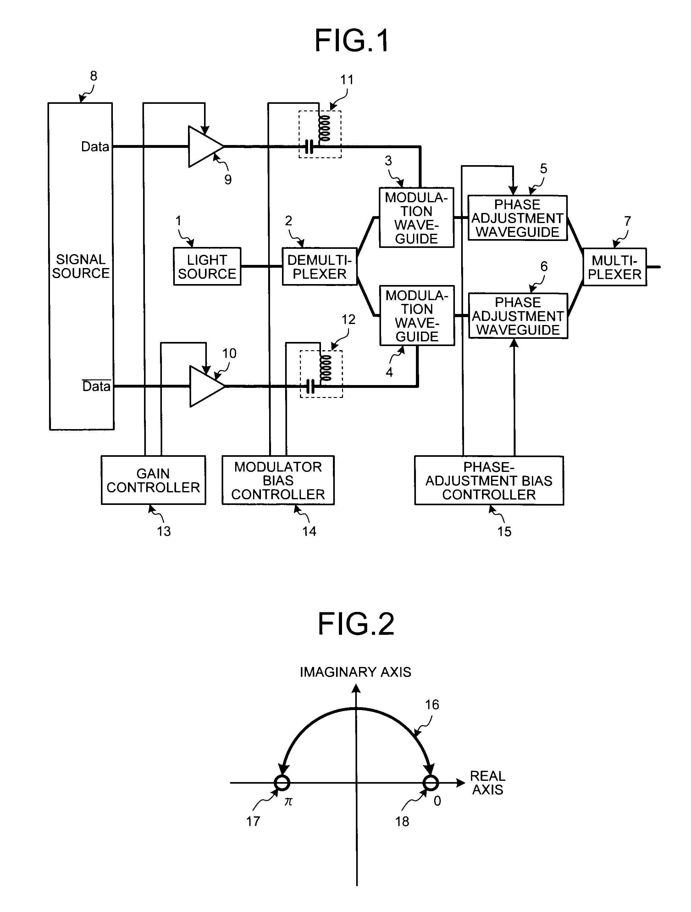
[0028]FIG. 1 is an example of a configuration of an optical modulator according to a first embodiment of the present invention. As shown in FIG. 1, the optical modulator according to the first embodiment is a semiconductor Mach-Zehnder modulator, and includes a light source 1, a demultiplexer 2, modulation waveguides 3 and 4 (first and second modulation waveguides), phase adjustment waveguides 5 and 6, a multiplexer 7, a signal source 8, drivers (amplifiers) 9 and 10, bias tees (bias applying units) 11 and 12, a gain controller 13, a modulator bias controller 14, and a phase-adjustment bias controller 15. While an example in which the optical modulator is a semiconductor Mach-Zehnder modulator is described in the first embodiment, t...


PUM

PropertyMeasurementUnit
phaseaaaaaaaaaa
voltagesaaaaaaaaaa
electric signalaaaaaaaaaa

Abstract

An optical modulator includes first and second modulation waveguides, a demultiplexer, first and second phase adjustment waveguides that changes phases of a light of the first and second modulation waveguides, a multiplexer that combines light outputs from the first and second phase adjustment waveguides, a gain controller and a modulator bias controller in which voltages of the first and second modulation signals are controlled so that a result of adding light from the first modulation waveguide to light from the second modulation waveguide where light from the first modulation waveguide has a predetermined phase is equal to a result of adding light from the first modulation waveguide to light from the second modulation waveguide where light from the second modulation waveguide has a predetermined phase. A phase-adjustment bias controller that controls phase amounts changed by the first and second phase adjustment waveguides so as to cancel phase errors.

Description

BACKGROUND OF THE INVENTION[0001]1. Field of the Invention[0002]The present invention relates to an optical modulator and an optical modulation method.[0003]2. Description of the Related Art[0004]As a phase modulator used for high-speed optical communications, a Mach-Zehnder modulator has been commercially available. Modulators made of ferroelectric such as lithium niobate are conventionally used as the Mach-Zehnder modulators (for example, see Japanese Patent Application Laid-open No. 2009-171634). Furthermore, semiconductor Mach-Zehnder modulators made of semiconductor are increasingly put to practical use for downsizing and power saving of devices (for example, see “2010, the transactions of the IEICE society conference”, Electronics C-3-54, 2010).[0005]For example, the semiconductor Mach-Zehnder modulator is configured as follows. A first modulation waveguide constitutes a first arm and a second modulation waveguide constitutes a second arm. A demultiplexer splits a light output...

Claims


Application Information

Patent Timeline
Patent Type & Authority Applications(United States)
IPC IPC(8): H01S3/063G02F1/035
CPCG02F1/0123H04B10/5053G02F1/225
Inventor MATSUDA, KEISUKESUGIHARA, TAKASHIMOCHIZUKI, KEITAARUGA, HIROSHI
Owner MITSUBISHI ELECTRIC CORP
Why Eureka
Try Eureka