Objective lens, optical head and optical disk device

a technology applied in the field of optical head and optical disk device, can solve the problems of increasing light intensity loss and other problems, and achieve the effect of suppressing light intensity loss and improving diffraction efficiency

Inactive Publication Date: 2012-12-20
PANASONIC CORP
View PDF8 Cites 0 Cited by
  • Summary
  • Abstract
  • Description
  • Claims
  • Application Information

AI Technical Summary

Benefits of technology

[0017]The present invention has been made in order to solve the problems described above, and an object thereof is to provide an objective lens, an optical head, and an opt...

Problems solved by technology

However, with the conventional synthetic resin objective lenses disclosed in Patent Literature 1 and Patent Literature 2, descriptions thereof are limited to a shape of a connecting surface in a case where a cross section of annular optical surfaces centered around an optical axis has an approximately sawtooth shape.
Furthermore, with an objective lens with a high numerical aperture such as that used for a BD, an incidence angle of a laser beam or, in other words, an angle formed by a surface perpendicular to an optical axis and a lens surface (a lens inclination angle) in...

Method used


Image

  • Objective lens, optical head and optical disk device
  • Objective lens, optical head and optical disk device
  • Objective lens, optical head and optical disk device

Examples


first embodiment

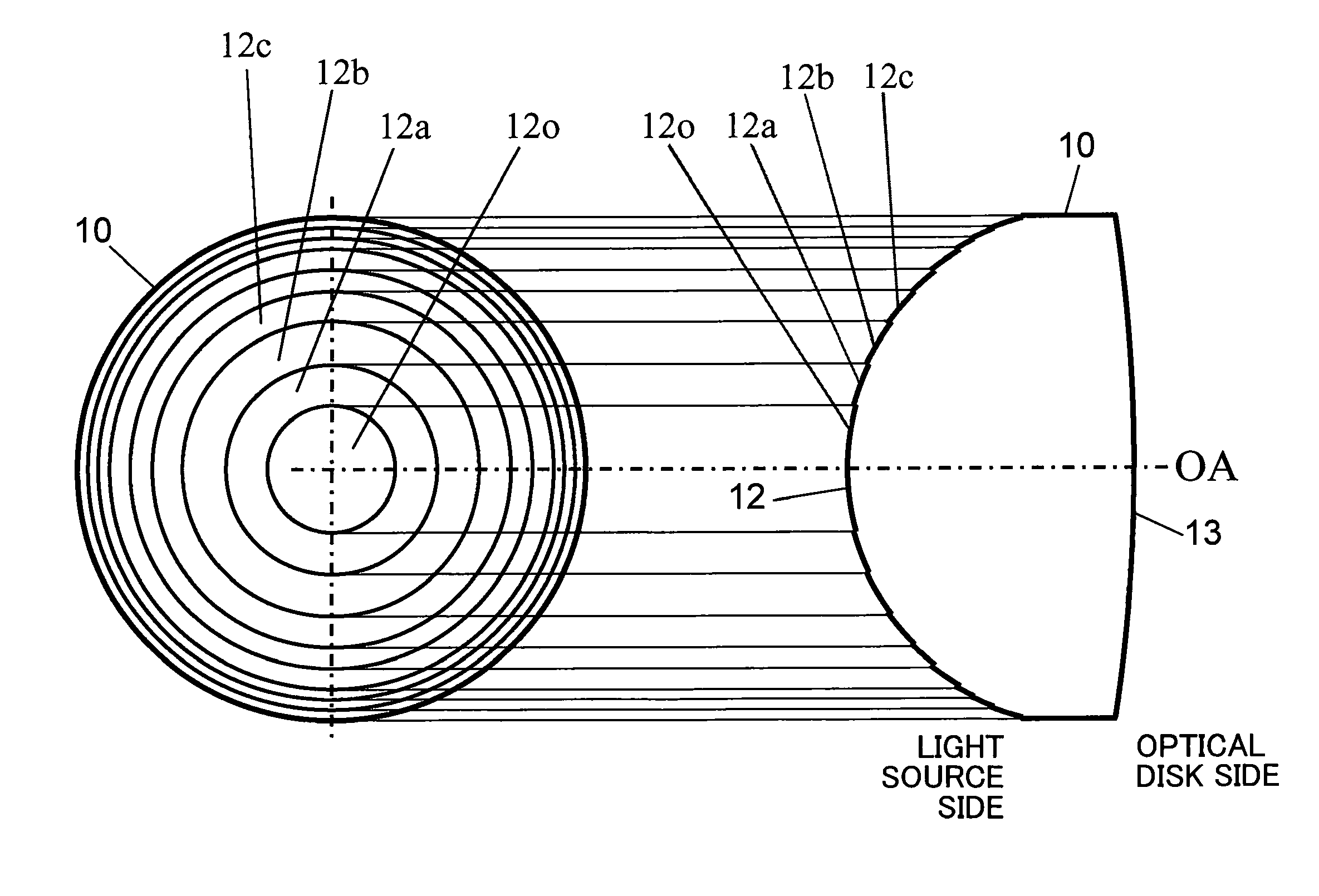
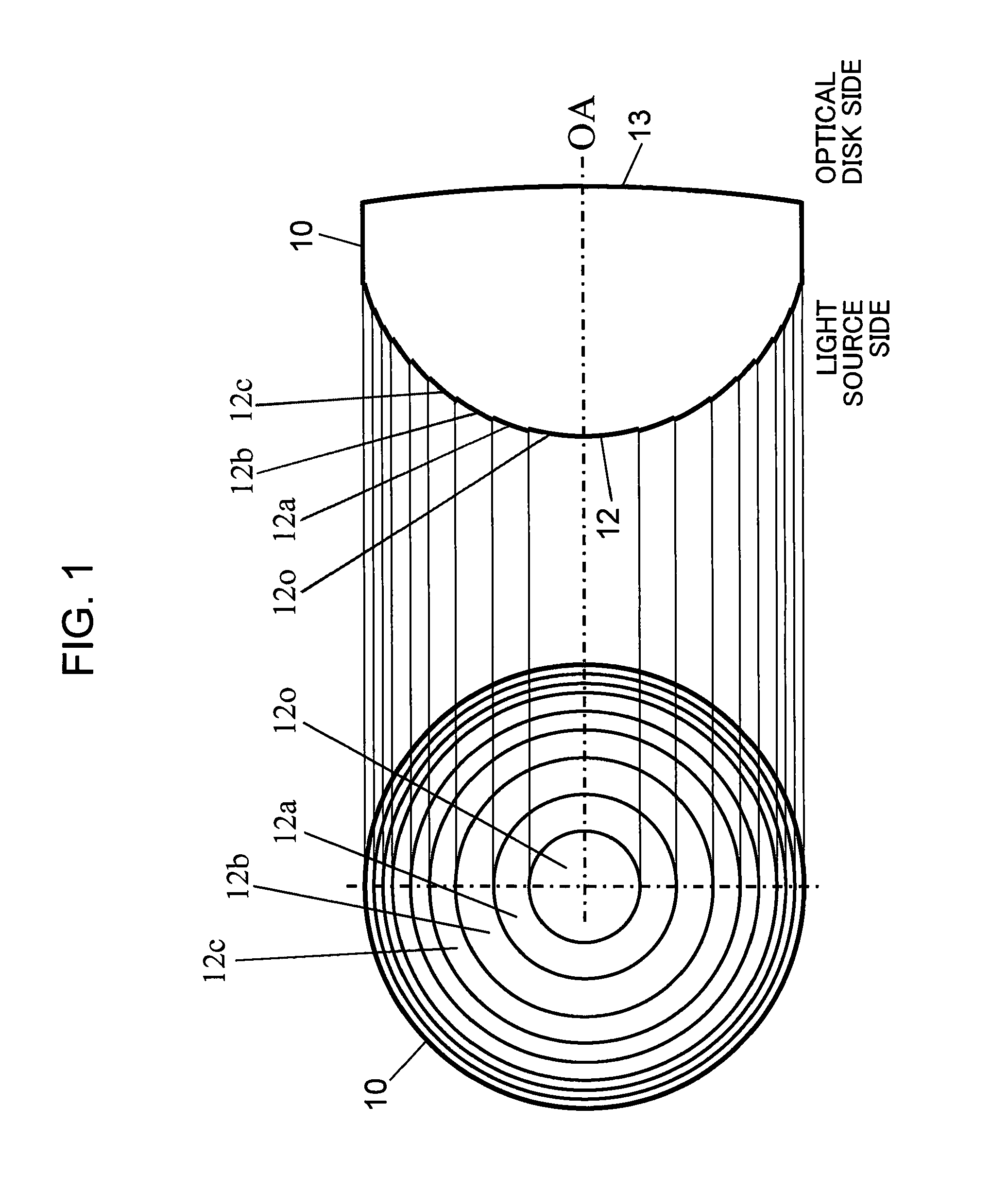
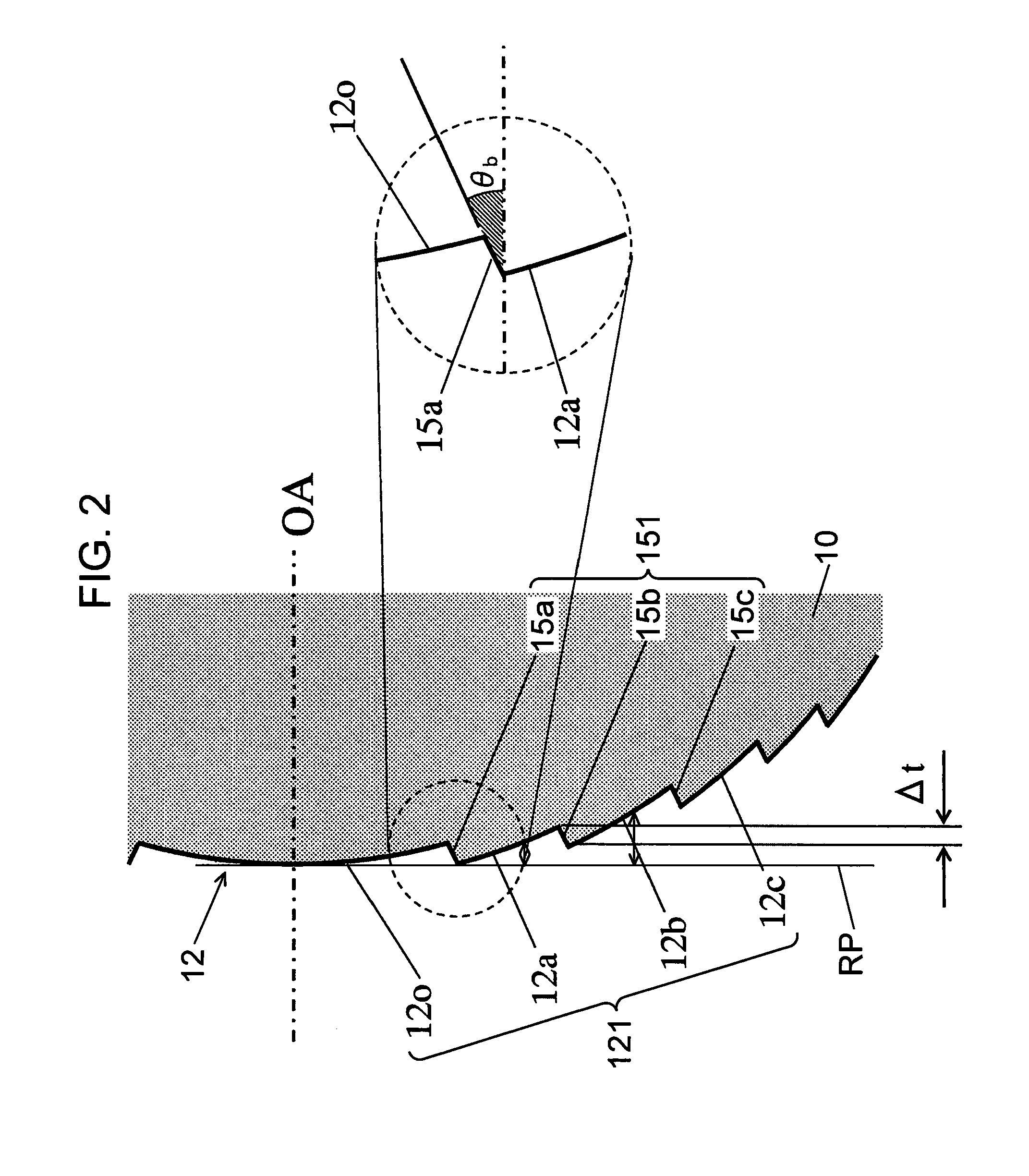
[0045]FIG. 1 is a diagram showing a configuration of an objective lens according to a first embodiment of the present invention. A left-hand side diagram in FIG. 1 is a plan view showing a configuration of a synthetic resin objective lens 10 according to the present first embodiment, and a right-hand side diagram in FIG. 1 is a sectional view showing a configuration of the objective lens 10. A lens surface 12 on a light source side (an incidence side of a laser beam) of the objective lens 10 comprises a spherical surface or an aspherical surface that constitutes a base. A sawtooth-shaped diffractive structure having a plurality of annular optical surfaces centered around an optical axis OA of the objective lens 10 is formed on the spherical surface or the aspherical surface that constitutes a base (hereinafter, collectively referred to as a base aspherical surface).

[0046]Meanwhile, a lens surface 13 on an optical disk side (an exit side of a laser beam) of the objective lens 10 whic...

second embodiment

[0098]FIG. 7 is a diagram showing a configuration of an objective lens according to a second embodiment of the present invention. A left-hand side diagram in FIG. 7 is a plan view showing a configuration of a synthetic resin objective lens 20 according to the present second embodiment, and a right-hand side diagram in FIG. 7 is a sectional view showing a configuration of the objective lens 20. A lens surface 22 on a light source side (an incidence side of a laser beam) of the objective lens 20 comprises a base aspherical surface. A stair-shaped diffractive structure having a plurality of annular optical surfaces centered around an optical axis OA of the objective lens 20 is formed on the base aspherical surface.

[0099]Meanwhile, a lens surface 23 on an optical disk side (an exit side of a laser beam) of the objective lens 20 which opposes the lens surface 22 is configured as a spherical surface or an aspherical surface.

[0100]FIG. 8 is a partially enlarged sectional view showing a vic...

third embodiment

[0141]FIG. 12 is a diagram showing a configuration of an objective lens according to a third embodiment of the present invention. A left-hand side diagram in FIG. 12 is a plan view showing a configuration of a synthetic resin objective lens 30 according to the present third embodiment, and a right-hand side diagram in FIG. 12 is a sectional view showing a configuration of the objective lens 30 according to the present third embodiment. A lens surface 32 on a light source side (an incidence side of a laser beam) of the objective lens 30 comprises a base aspherical surface. A stair-shaped diffractive structure having a plurality of annular optical surfaces centered around an optical axis OA of the objective lens 30 is formed on the base aspherical surface.

[0142]Meanwhile, a lens surface 33 on an optical disk side (an exit side of a laser beam) of the objective lens 30 which opposes the lens surface 32 is configured as a spherical surface or an aspherical surface.

[0143]The lens surface...


PUM


Abstract

A lens surface (22) of an objective lens (20) includes an optical surface (221) formed of a plurality of annular optical surfaces (22a, 22b, 22c, and 22d) which include an approximately stair-shaped cross section and which are annularly partitioned centered around an optical axis (OA) of the objective lens (20), and a plurality of connecting surfaces (251) that connect the plurality of mutually adjacent annular optical surfaces to each other. The plurality of connecting surfaces (251) include cylindrical connecting surfaces (25b and 25c) formed of a cylindrical surface centered around the optical axis (OA) and a conical connecting surface (26a) formed of a conical surface centered around the optical axis (OA), and the conical connecting surface (26a) connects the annular optical surface (22c) and the annular optical surface (22d).

Description

TECHNICAL FIELD[0001]The present invention relates to an objective lens having an optical surface formed of a plurality of partitioned surfaces annularly partitioned centered around an optical axis, an optical head using the objective lens, and an optical disk device using the optical head.BACKGROUND ART[0002]With the increase in practical application of blue-violet semiconductor lasers, a Blu-ray Disc (hereinafter BD) that is an high-density, large-capacity optical information recording medium (hereinafter, also referred to as an optical disk) with a same size as an CD (Compact Disc) and a DVD (Digital Versatile Disc) is being put to practical use. A BD is an optical disk in which information is recorded onto or reproduced from an information recording surface having a light transmission layer with a thickness of approximately 0.1 mm using a blue-violet laser light source that outputs a laser beam with a wavelength of around 400 nm and an objective lens with a numerical aperture (N...

Claims


Application Information

Patent Timeline
IPC IPC(8): G11B7/00G02B3/02G11B7/1353G11B7/1374
CPCG02B5/1895G11B7/1353G11B7/1374G02B5/1876
Inventor YAMASAKI, FUMITOMOKOMMA, YOSHIAKIHAYASHI, KATSUHIKOTAKASU, YOSHIFUMI
Owner PANASONIC CORP
Why Eureka
Try Eureka