Electrothermal heater mat

a heater mat and electro-thermal technology, applied in the direction of ohmic-resistance heating, electrical equipment, aircraft power plants, etc., can solve the problems of increasing drag, reducing the ability of an aerofoil to perform the intended function, and undesirable ice formation in flight on the external surface of the aircraft, so as to reduce the risk of de-lamination and optimize the strength of the lamination

Active Publication Date: 2013-01-03
GKN AEROSPACE SERVICES LTD
View PDF10 Cites 18 Cited by
  • Summary
  • Abstract
  • Description
  • Claims
  • Application Information

AI Technical Summary

Benefits of technology

[0020]Preferably, all of the dielectric layers comprise the same dielectric material. This optimises the strength of the lamination between the dielectric layers when they are heated and pressed together, and reduces the risk of de-lamination at the interfaces between the layers.
[0021]In our current embodiments, the spraying produces

Problems solved by technology

For an aircraft, the in-flight formation of ice on the external surface of the aircraft is undesirable.
The ice destroys the smooth flow of air over the aircraft surface, increases drag and decreases the ability of an aerofoil to perform its intend

Method used


Image

  • Electrothermal heater mat
  • Electrothermal heater mat
  • Electrothermal heater mat

Examples


Embodiment Construction

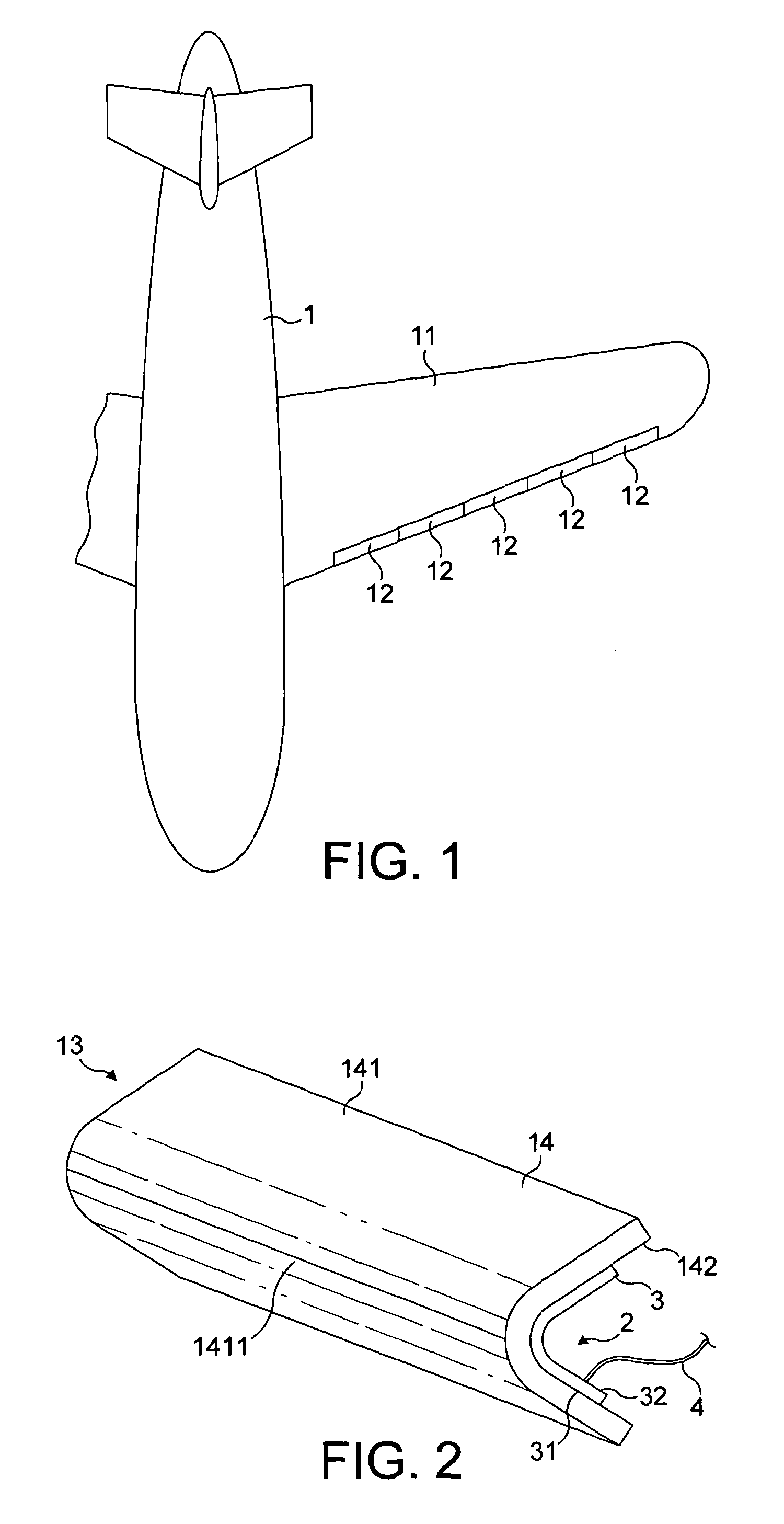
[0071]FIG. 1 is a plan view of an aircraft 1 having a wing 11 along the leading (forward) edge of which are positioned five wing slats 12. Each wing slat 12 incorporates an electrothermal ice protection system.

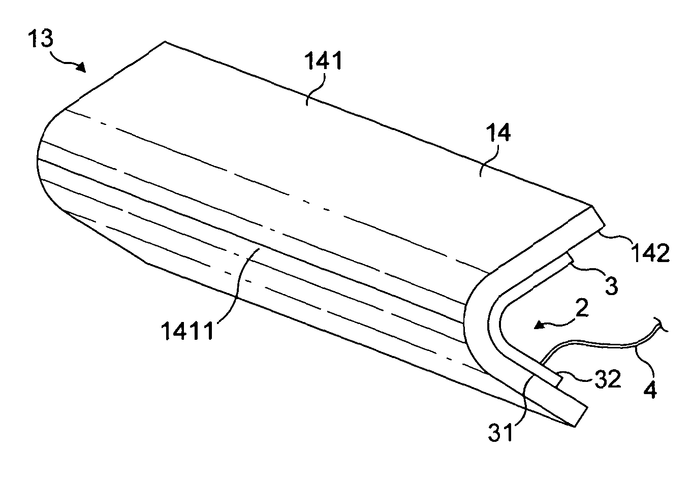
[0072]FIG. 2 is a diagrammatic perspective view of a demountable nose skin 13 of one of the wing slats 12 of FIG. 1. The configuration of the nose skin 13 may be generally the same as in EP-A-1,757,519 (GKN Aerospace) which discloses a wing slat having a demountable forward section comprising a nose skin.

[0073]The nose skin 13 comprises an erosion shield 14 and an electrically-powered heater 2.

[0074]The heater 2 comprises a heater blanket or mat 3 and a bundle of connectors 4 which connect the heater mat 3 to the power supply and control electronics of the aircraft 1.

[0075]The erosion shield 14 is generally rectangular and has a front surface 141 which is convexly curved and a rear surface 142 which is concavely curved. An apex 1411 of the front surface 141 provides the leadin...


PUM


Abstract

An electrothermal heater mat (3) is provided for an ice protection system for an aircraft (1) or the like. The heater mat (3) is a laminated heater mat and comprises dielectric layers (50-58), a heater element (501) and a conductive ground plane (71-74) for detecting a fault with the heater element (501). The dielectric layers (50-58) are made of thermoplastic material, and the ground plane (71-74) is formed by spraying metal such as copper onto the thermoplastic material of one of the dielectric layers.

Description

FIELD OF THE INVENTION[0001]The present invention relates generally to an electrothermal ice protection system suitable for use in an aircraft or other aerodynamic structure such as a blade of a wind turbine to prevent ice from forming and / or to remove ice that has already formed. These two functions may be termed anti-icing and de-icing, respectively.BACKGROUND OF THE INVENTION[0002]For an aircraft, the in-flight formation of ice on the external surface of the aircraft is undesirable. The ice destroys the smooth flow of air over the aircraft surface, increases drag and decreases the ability of an aerofoil to perform its intended function.[0003]Also, built-up ice may impede the movement of a movable control surface such as a wing slat or flap. Ice which has built up on an engine air inlet may be suddenly shed in large chunks which are ingested into the engine and cause damage.[0004]It is therefore common for aircraft, and particularly commercial aircraft, to incorporate an ice prote...

Claims


Application Information

Patent Timeline
IPC IPC(8): H05B3/00
CPCB64D15/12B64D2033/0233H05B2203/033H05B2203/013H05B2203/017H05B3/36
Inventor LEWIS, STUART MARTINWINTER, NICHOLAS JOHN
Owner GKN AEROSPACE SERVICES LTD
Why Eureka
Try Eureka