Polyaxial bone anchoring device

a polyaxial bone and bone technology, applied in the field of polyaxial bone anchoring devices, can solve the problems of difficult alignment of the receiving part and the insertion of the rod in more complex clinical applications, and achieve the effects of convenient manufacturing, large manufacturing tolerances, and simple design

Active Publication Date: 2013-04-18
BIEDERMANN TECH GMBH & CO KG
View PDF56 Cites 39 Cited by
  • Summary
  • Abstract
  • Description
  • Claims
  • Application Information

AI Technical Summary

Benefits of technology

[0011]The polyaxial bone anchoring device according to embodiments of the invention comprises only few parts which are each of simple design, and where relatively large manufacturing tolerances are possible. A mechanism utilized to frictionally maintain the head before locking is free from any spring members or portions. This may facilitate easier manufacturing of the polyaxial bone anchoring device. Furthermore, existing receiving parts and pressure elements can be used without substantially modifying their forms. For example, it is possible to change existing crimp bores to threaded through bores.
[0012]An amount of preload exerted onto the head by the pressure element or member can be exactly predefined in a simple manner, for example, by selecting a position and shape of the bores and a shape of the set screw or screws, and furthermore by a force applied by the set screw or screws that is dependent on how deep the screws are advanced. By means of the set screws, a stepless adjustability of the pressure which is exer...

Problems solved by technology

However, when the head of the bone anchoring element remains freely pivotable with respect to the receiving part before locking the head in a final angular position, alignment o...

Method used


Image

  • Polyaxial bone anchoring device
  • Polyaxial bone anchoring device
  • Polyaxial bone anchoring device

Examples


first embodiment

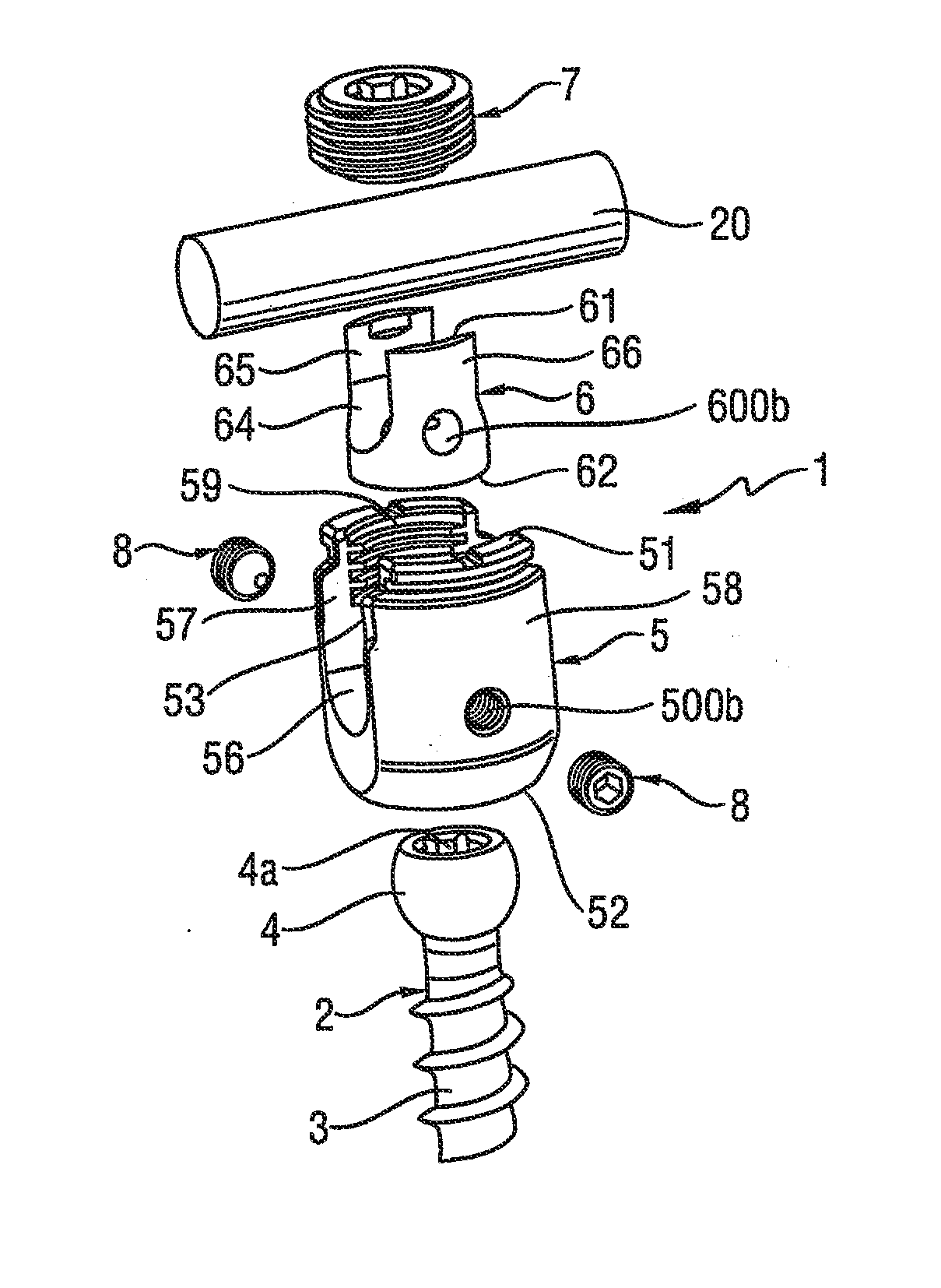
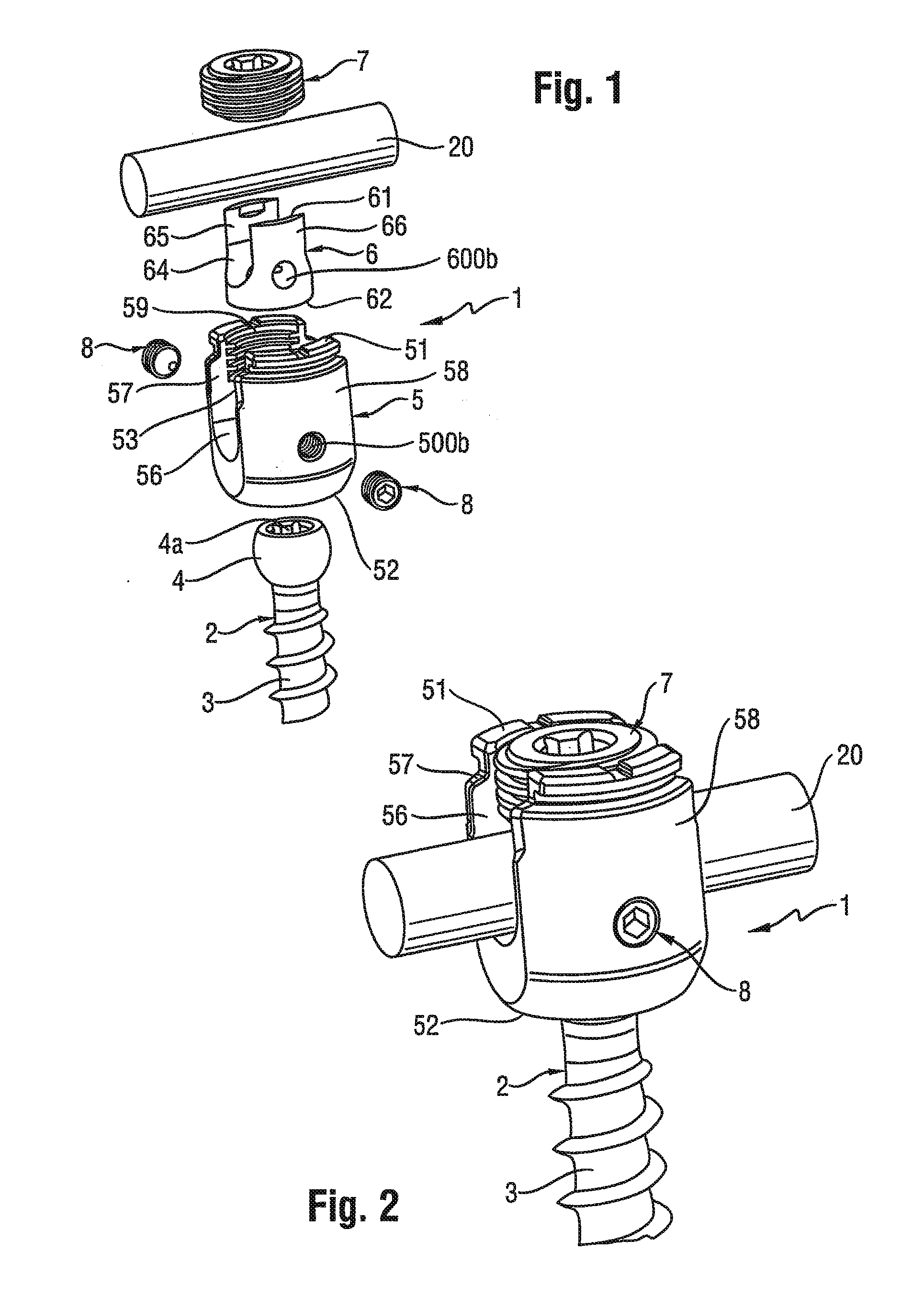
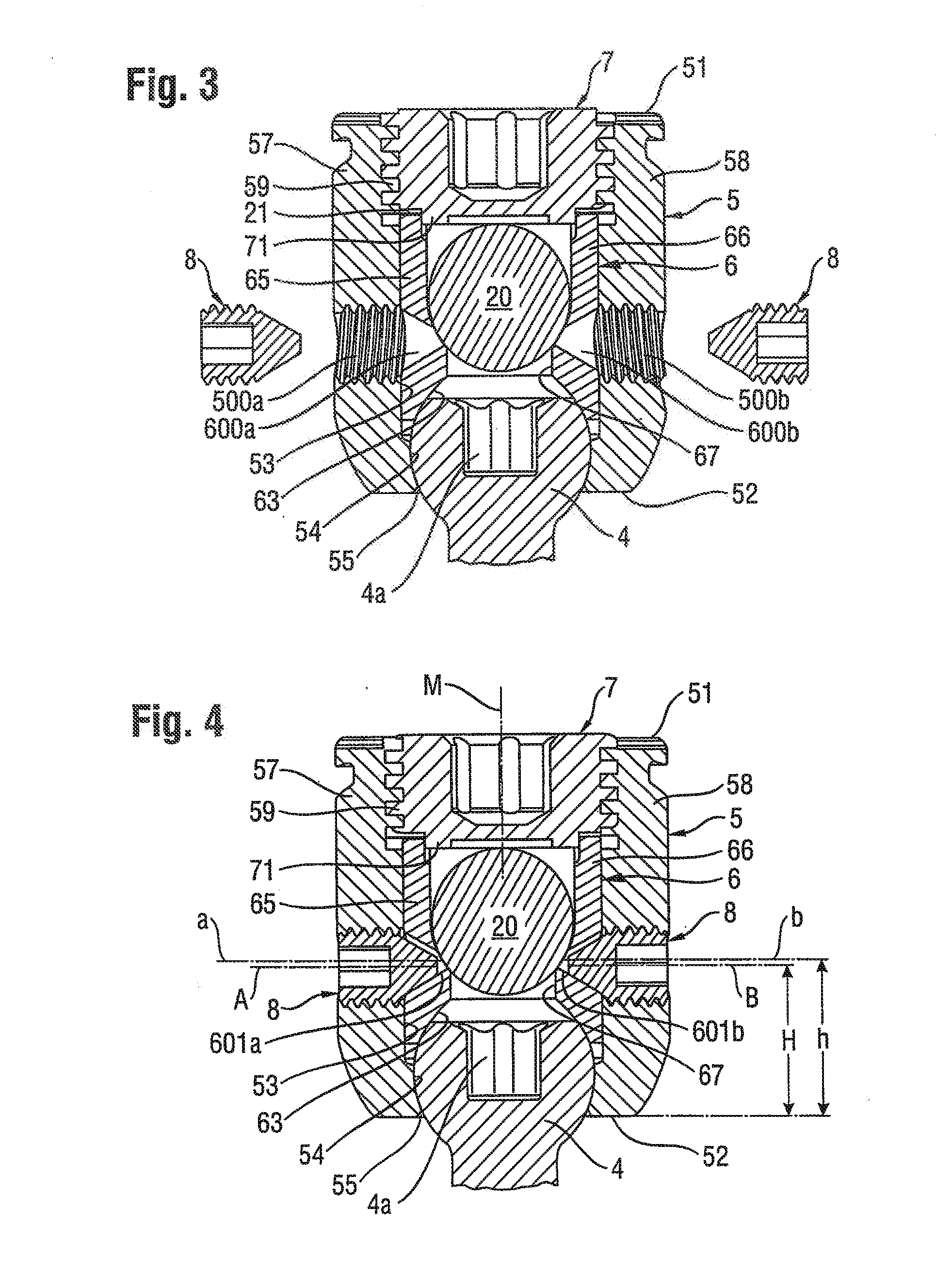
[0036]A polyaxial bone anchoring device 1 as shown in FIGS. 1 to 4 includes a bone anchoring element 2 in the form of a screw member having a threaded shaft 3 and a head 4. The head 4 is generally spherical and includes a recess 4a at its free end for engagement with a tool to insert the threaded shaft 3 into a bone. The bone anchoring device 1 further includes a receiving part 5 for connecting the anchoring element 2 to a rod 20. A pressure element 6 is arranged in the receiving part 5 on top of the head 4 (as seen, for example, in FIGS. 3 and 4). For securing the rod 20 in the receiving part 5, and in some embodiments, for exerting pressure onto the head 4, a locking device, for example an inner screw 7, which cooperates with the receiving part 5, is provided.

[0037]The receiving part is a substantially cylindrical one piece part and has a top end 51 and a bottom end 52. A passageway extending from the top end 51 to the bottom end 52 is formed by a coaxial bore 53 followed by a se...

third embodiment

[0049] shown in FIG. 14, bore holes 600a″, 600b″ can have, for example, a substantially rectangular cross-section.

fourth embodiment

[0050]According to a shown in FIG. 15, a cross-section of bore holes 600a′″, 600b′″ of the pressure element 6″ can be, for example, trapezoidal, with an inclined lower surface 601a′″, 601b′″ for engagement with truncated tapered surfaces of set screws 8″


PUM


Abstract

A polyaxial bone anchoring device includes an anchoring element having a shaft and a head, a receiving part having a first end and a second end, a bore extending from the first end towards the second end, a seat for receiving the head, and at least one threaded through hole transverse to the bore, a pressure element to exert pressure onto the head, such that the head is pivotable and can be locked at an angle relative to the receiving part, the pressure element having at least one hole configured to at least partially align with the through hole, and at least one set screw threadable into the through hole to engage the pressure element at the hole such that a force is exerted by the pressure element onto the head that maintains the head at an adjustable angular position relative to the receiving part by friction.

Description

CROSS-REFERENCE TO RELATED APPLICATION(S)[0001]The present application claims the benefit of U.S. Provisional Patent Application Ser. No. 61 / 525,093, filed Aug. 18, 2011, the contents of which are hereby incorporated by reference in their entirety, and claims priority to European Patent Application EP 11 178 034.2, filed Aug. 18, 2011 the contents of which are hereby incorporated by reference in their entirety.BACKGROUND[0002]1. Field of the Invention[0003]The invention relates to a polyaxial bone anchoring device for anchoring a stabilization rod relative to a bone or a vertrebra. The bone anchoring device includes an anchoring element, a receiving part for receiving a head of the anchoring element and for receiving a stabilization rod to be connected to the anchoring element. The anchoring element is pivotably connected to the receiving part and can be locked at an angle by exerting pressure onto the head via a pressure element that is arranged in the receiving part. The pressure ...

Claims


Application Information

Patent Timeline
IPC IPC(8): A61B17/70A61B17/86
CPCA61B17/70A61B17/7035A61B17/8605A61B17/7032A61B17/7034A61B17/7037A61B17/725A61F2002/30495
Inventor BIEDERMANN, TIMOBIEDERMANN, LUTZ
Owner BIEDERMANN TECH GMBH & CO KG
Why Eureka
Try Eureka