Adjustable Position Blocking Device for Sliding Closures

Inactive Publication Date: 2013-07-18
MCEACHERN MARC FRLIN
View PDF16 Cites 10 Cited by
  • Summary
  • Abstract
  • Description
  • Claims
  • Application Information

AI Technical Summary

Benefits of technology

[0017]In addition, the slider comprises two components (a universal slider and a blocking module), and a modular attachment means which permits the end-user to easily attach blocking modules of different form and function to the universal slider base which comprises a standardized interlocking attachment end. The universal slider constitutes a variable position attachment base of the slider which attaches to the track. The blocking module which comprises a complimentary interlocking attachment end, constitutes a blocking component of the slider. Customized blocking modules can be easily developed for different closure constructions, for example, sliding windows versus sliding doors. In addition, blocking modules may incorporate an electronic device that can perform multiple functions. For example, when the closure is opened and contacts the device, a switch mechanically attached to a bumper on the blocking device closes, activating the electronic device. An electronic device could be an onboard sound, or light device to alert the possibility of intrusion, or media recording devices to record pictures, video or audio of the intruder, or an onboard wireless device that would communicate with another wireless device, or system to alert the possibility of intrusion, or a combination thereof.
[0018]Accordingly, several advantages of o

Problems solved by technology

One drawback of such fasteners, especially those that exist in older homes, is that the fastener can be easily popped off, broken or disengaged from the outside allowing a would-be criminal to enter therethrough.
Another drawback of many such fasteners is that the fastener can only be engaged when the closure is fully closed.
If the closure is partially opened to allow for external air circulation, the fastener cannot be engaged and is thus rendered useless as a security device.
Although Fiedler's device can be placed anywhere along the track and does not require an invasive installation, the vice mechanism is inherently weak.
With any moderate and repeated force in the opening direction of the sliding closure, the Fiedler device will slip along or disengage from the track, potentially damaging the track in the process.
Although such bar-type blocking devices provide added security, they are large, unsightly and like Bentley's proposed device, the installation requires an invasive mount wit

Method used


Image

  • Adjustable Position Blocking Device for Sliding Closures
  • Adjustable Position Blocking Device for Sliding Closures
  • Adjustable Position Blocking Device for Sliding Closures

Examples


first embodiment

DETAILED DESCRIPTION—FIG. 1 TO FIG. 9B—FIRST EMBODIMENT

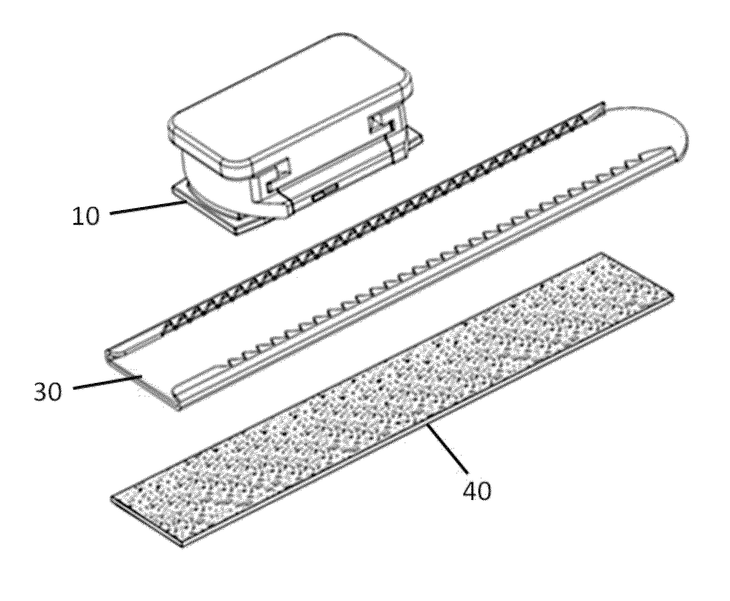
[0038]In FIG. 1, there is shown a perspective view of one embodiment, partially disassembled. The embodiment includes a multi-position blocking slider 10, a track 30, and very high bonding double-sided adhesive tape 40.

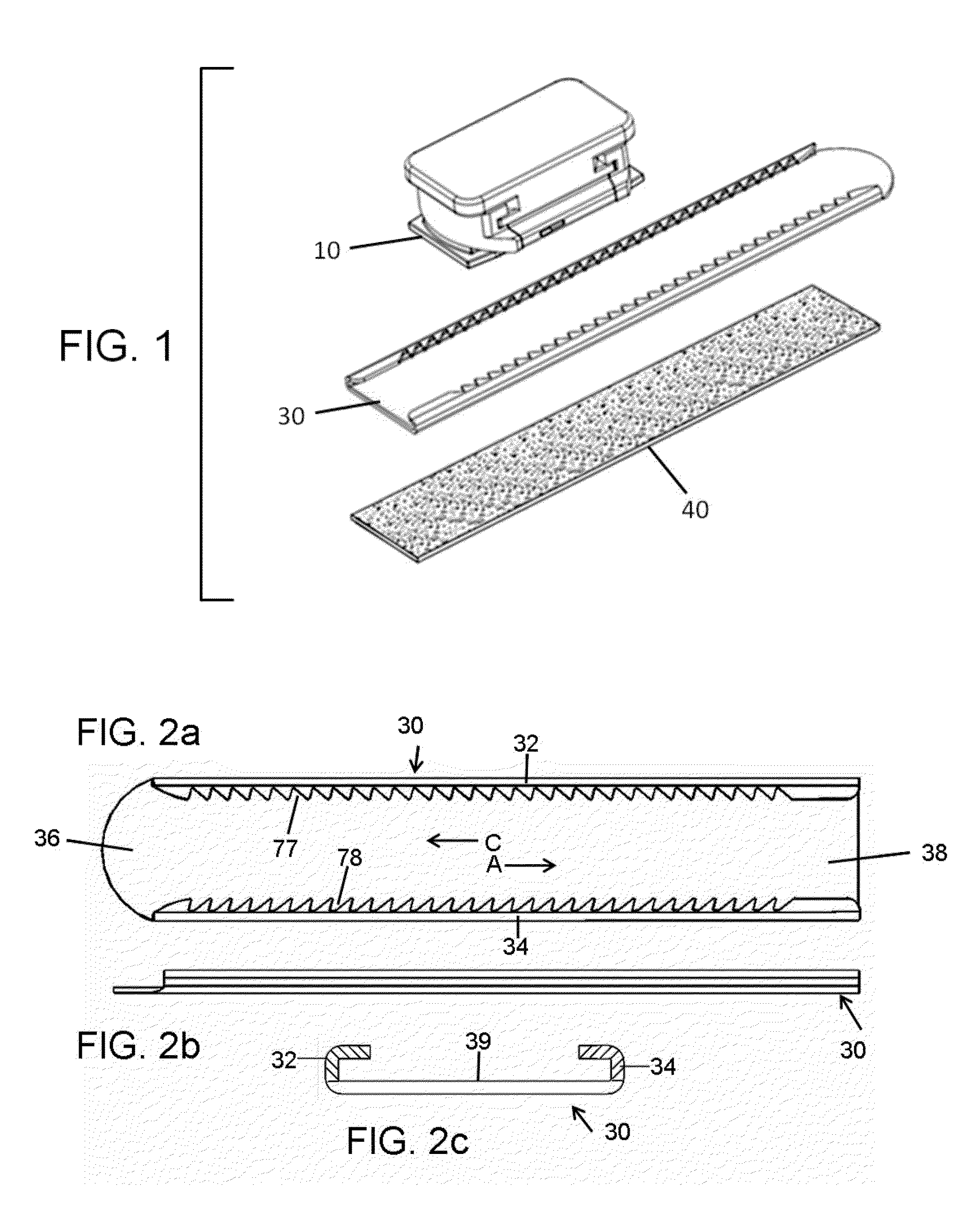
[0039]In FIGS. 2a to 2c, there is shown a top, lateral, and rear view, respectively, of track 30 in accordance with the embodiment of FIG. 1. Track 30 is an elongated body that comprises two ends; one designated the track entrance 36, and the other the track front 38. The forward direction A is the direction from the track entrance 36 towards the track front 38. The reverse direction C is in the opposing direction of A. In addition, track 30 comprises two elongated hook-shaped edges named the left edge 32 and the right edge 34 curving to one side forming a channel with asymmetric but uniform grooves (77 and 78) shaped into each edge. The side with hook-shaped edges (32 and 34) is designated the attachment side 39....


PUM


Abstract

An adjustable position blocking device for sliding closures that firmly attaches to a glass pane of a closure and limits the sliding translation of the sliding panels of the closure. One embodiment comprises an elongated track (30) which adheres to a glass pane with very high bonding double-sided tape (40). The one embodiment also comprises a blocking slider (10) that adjustably attaches to track (30) at a plurality of track positions and is substantially tall to block the sliding translation of the sliding panels. Slider (10) comprises a modular attachment means that permits the slider (10) to be customized with blocking modules (22, 86, 96) of different form and function. In addition, one embodiment comprises a blocking module (96) which integrates an electronic device to detect the opening of a sliding closure and alert a user, a remote device or a remote system.

Description

CROSS-REFERENCE TO RELATED APPLICATIONS[0001]Not ApplicableSTATEMENT REGARDING FEDERALLY SPONSORED RESEARCH OR DEVELOPMENT[0002]Not ApplicableREFERENCE TO SEQUENCE LISTING, A TABLE, OR A COMPUTER PROGRAM LISTING COMPACT DISK APPENDIX[0003]Not ApplicableBACKGROUNDPRIOR ART[0004]The following is a tabulation of some prior art that presently appears relevant:U.S. PatentsPat. No.Kind CodeIssue DatePatentee3,078,524AFeb. 26, 1963Minick5,125,699AJun. 30, 1992Dinan5,409,271AApr. 25, 1995HoffmannU.S. Patent Application PublicationsPublication Nr.Kind CodePubl. DateApplicant20070194579A1Aug. 27, 2007Fiedler20070209414A1Sep. 13, 2007Bentley[0005]Additional examples of prior art for sliding closure security devices may be seen in U.S. Pat. Nos. 3,938,839; 4,171,835; 4,274,666; 4,607,253; 5,437,486; 5,620,215; 6,264,252; 7,887,105 and 7,463, 577 B2.[0006]Solutions for sliding window security devices include window latches and locks which are designed to prevent the sliding window from being ope...

Claims


Application Information

Patent Timeline
IPC IPC(8): E05B65/08E05C19/00
CPCE05B65/08E05B2045/063E05B65/0025E05C2007/007E05B15/0046E05B15/1607E05C17/60Y10T292/391Y10T70/5173Y10T292/42Y10T70/40Y10T70/5181Y10T292/34E05C17/48
Inventor MCEACHERN, MARC FRANKLIN
Owner MCEACHERN MARC FRLIN
Why Eureka
Try Eureka