Internal combustion engine

a combustion engine and combustion chamber technology, applied in combustion engines, non-fuel substance addition to fuel, charge feed systems, etc., can solve the problems of gas recirculation rate, inability to always be maintained as desired, acceleration behavior deterioration of vehicles provided with such engines, etc., to prevent fouling

Active Publication Date: 2013-09-12
MOTOREN & TURBINEN UNION FRIEDRICHSHAFEN GMBH
View PDF18 Cites 17 Cited by
  • Summary
  • Abstract
  • Description
  • Claims
  • Application Information

AI Technical Summary

Benefits of technology

[0017]It is also to be understood that the charging fluid is basically charge air. Still, a recirculation line of the exhaust gas recirculation system may be so connected to the charging fluid side of the internal combustion engine that the recirculated exhaust gas can be supplied to the charging fluid side at different locations as needed. For example, exhaust gas can be supplied to the charging fluid side at a secondary side of a high pressure compressor and/or a high pressure heat exchanger in particular directly at the charging fluid manifold of the internal comb

Problems solved by technology

It has been found that at low speeds comparatively high exhaust gas recirculation rates—for maintaining NOx limits—cannot always be maintained as desired.
It has also been found that—with high exhaust gas recirculation rates—insufficient amounts of fresh air may be contained in the charge air supplied to the engine, which may result in

Method used


Image

  • Internal combustion engine
  • Internal combustion engine
  • Internal combustion engine

Examples


Embodiment Construction

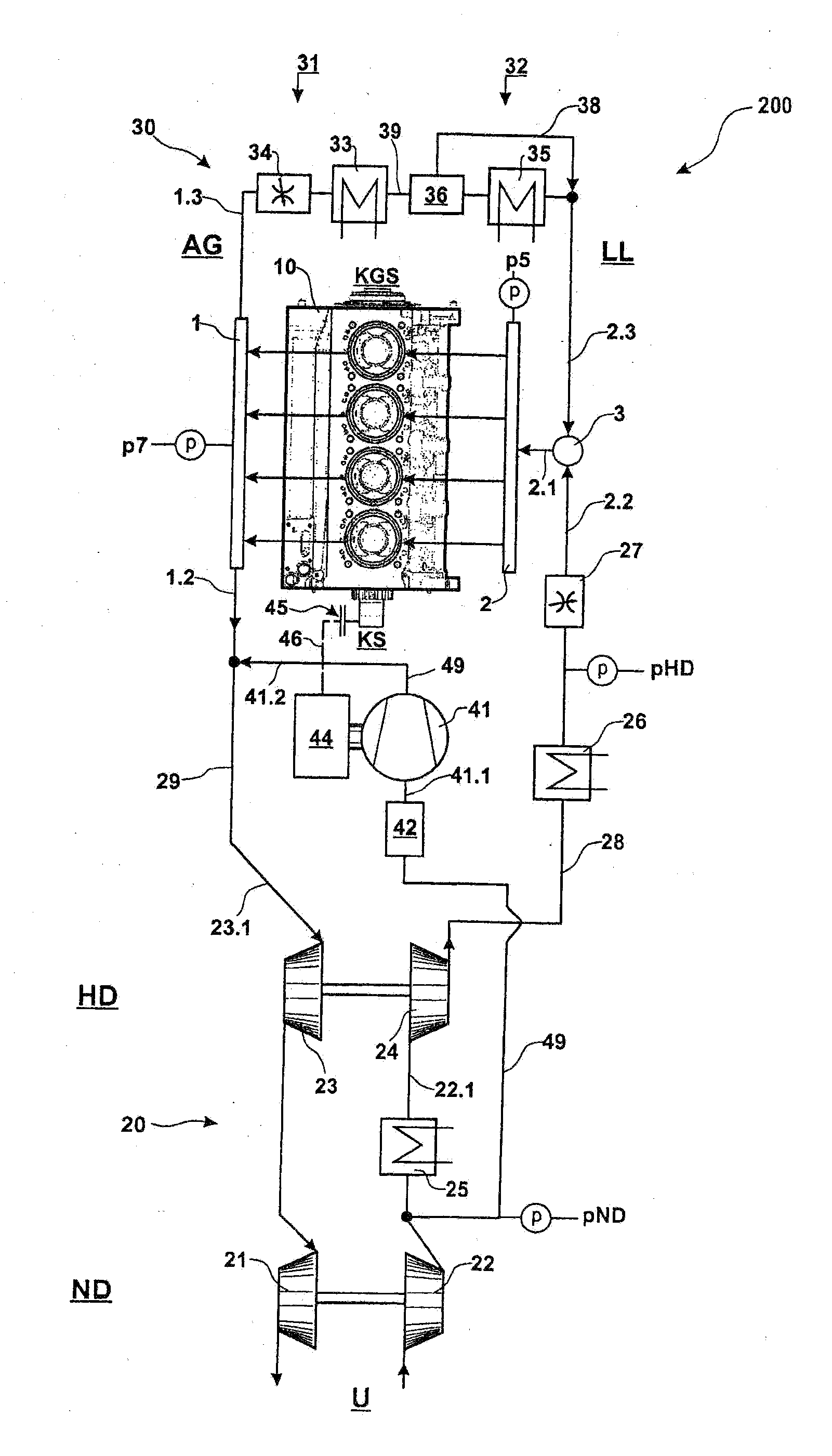
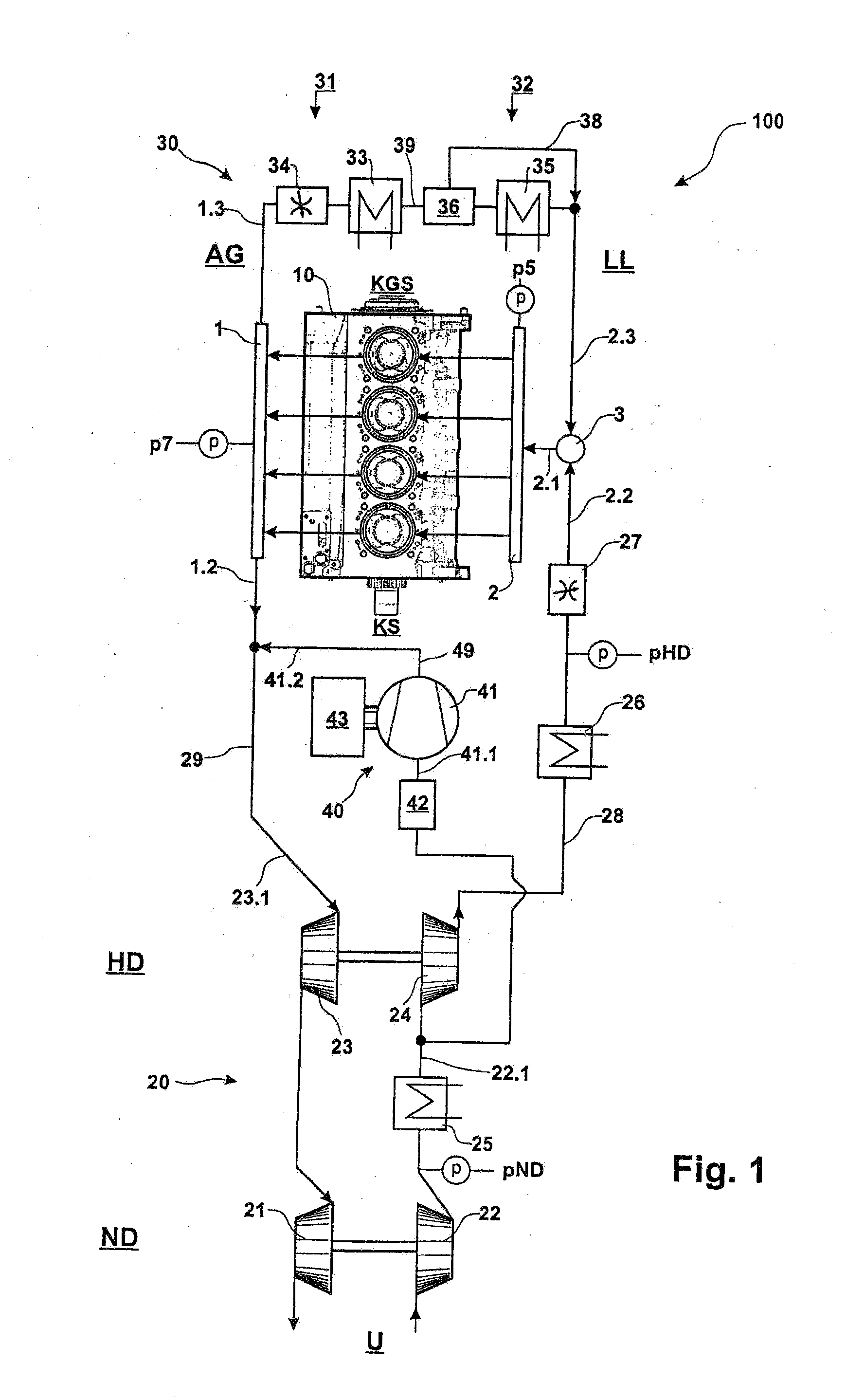
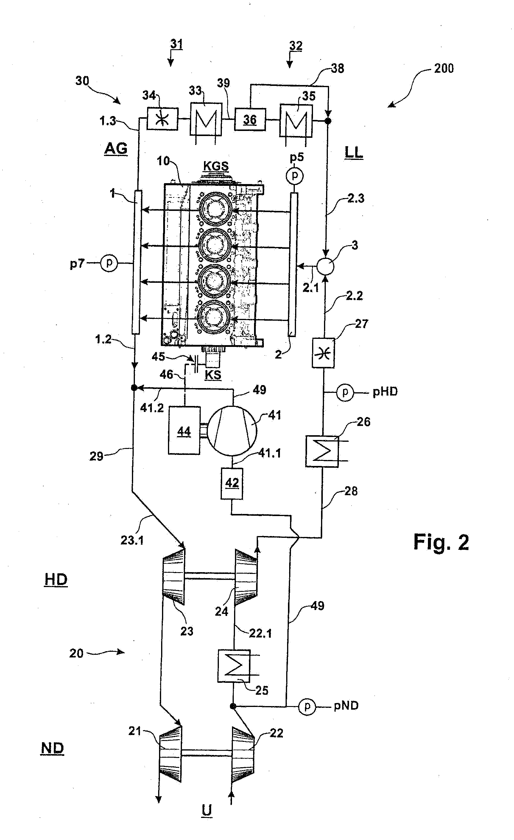
[0023]FIG. 1 shows an internal combustion engine 100 with an engine 10 and a charging system comprising an exhaust gas turbocharger 20 and an exhaust gas recirculation system 30. The engine 10 is shown, in the form, of a four-cylinder inline engine as a fast running engine operating at speeds in the range of 800 to 2500 rpm. The engine 10 has an exhaust gas side AG for conducting exhaust gas from the exhaust gas manifold 1 of the engine 10 via an exhaust line 1.2 to the exhaust gas turbocharger 20 and an exhaust gas recirculation line 1.3 extending between the exhaust gas manifold 1 and the exhaust gas recirculation system 30. The engine also includes a charging fluid side LL for charging the engine 10 with a charging fluid via a charging fluid intake manifold 2. The charging fluid in the intake manifold 2 is here a mixture of charge air supplied via a charge air line 2.2 from the exhaust gas turbocharger 20 and exhaust gas supplied via a recirculation line 2.3 from the exhaust gas ...


PUM


Abstract

In an exhaust gas turbocharger system for charging an engine including a compressor arrangement at a charging fluid side LL and a turbine arrangement at an exhaust gas side AG, a further compressor which is driven by a separate controllable drive and whose primary side is connected to the charging fluid side LL while its secondary side is connected to the exhaust gas side is provided for compressing charge air taken from the charging fluid side and supply it to the exhaust gas side for assisting driving the exhaust gas turbines so as to maintain them at relatively high speeds in transition periods including engine idling.

Description

[0001]This is a Continuation-in-part application of pending international patent application PCT / EP2011 / 005310 filed Oct. 21, 2011 and claiming the priority of German patent application 10 2010 043 027.7 filed Oct. 27, 2010.BACKGROUND OF THE INVENTION[0002]The invention resides in an internal combustion engine comprising an engine with an exhaust gas side and a charge air side, a charging system including an exhaust gas turbocharger for charging the internal combustion engine with a compressor arrangement on the charge air side and a turbine arrangement on the exhaust gas side and a compressor having a primary side connected to the charge air side and a secondary side connected to the exhaust gas side. The invention also concerns a motor vehicle with an internal combustion engine.[0003]DE 198 37 978 A1 discloses an internal combustion engine with an exhaust gas turbocharger for a two-stage charging of an internal combustion engine and with exhaust gas recirculation wherein an exhaus...

Claims


Application Information

Patent Timeline
IPC IPC(8): F02M25/07
CPCF02B37/013F02B37/10Y02T10/121Y02T10/144F02B37/004F02M25/0739F02B37/168F02M25/0707F02M25/0711F02M25/0732F02B37/04F02M26/05F02M26/08F02M26/24F02M26/34Y02T10/12
Inventor HEIERMANN, JOERG
Owner MOTOREN & TURBINEN UNION FRIEDRICHSHAFEN GMBH
Why Eureka
Try Eureka