Luminescent-oled light collector signage panel

a technology of light collectors and signage panels, applied in the field of light collectors, can solve the problems of inability to clearly see the images of signage systems, high energy consumption of energy consumption, etc., and achieve the effect of increasing brightness

Inactive Publication Date: 2013-11-07
SIGNIFY HLDG BV
View PDF25 Cites 9 Cited by
  • Summary
  • Abstract
  • Description
  • Claims
  • Application Information

AI Technical Summary

Benefits of technology

[0005]The general concept behind the invention is the particular configuration of a light emitting structure and a patterned (and thus discontinuous) semi-transparent layer between which a luminescent material is arranged so that environmental light incident thr

Problems solved by technology

The lamps functioning as backlights or as side emissive lamps usually emit the light continuously once turned on so that their energy consumption is quite high.
Further, if there is a clock time

Method used


Image

  • Luminescent-oled light collector signage panel
  • Luminescent-oled light collector signage panel
  • Luminescent-oled light collector signage panel

Examples


Embodiment Construction

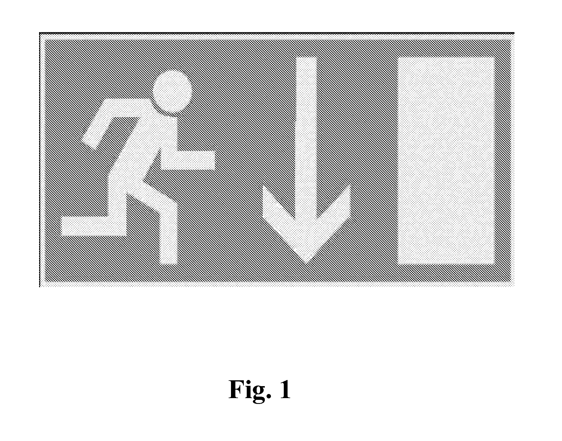
[0039]FIG. 1 depicts an example of a signage panel, for example, for pointing to an emergency exit. The image of the signage comprises, e.g., three elements (in FIG. 1: a running man, an arrow, and a rectangle). According to the invention, elements of an image may be formed by using a discontinuous semi-transparent layer on top of a luminescent material element so that portions are formed in which the luminescent material is not covered by the semi-transparent layer. These portions not covered by the semi-transparent layer may then appear as the elements of the image of the signage.

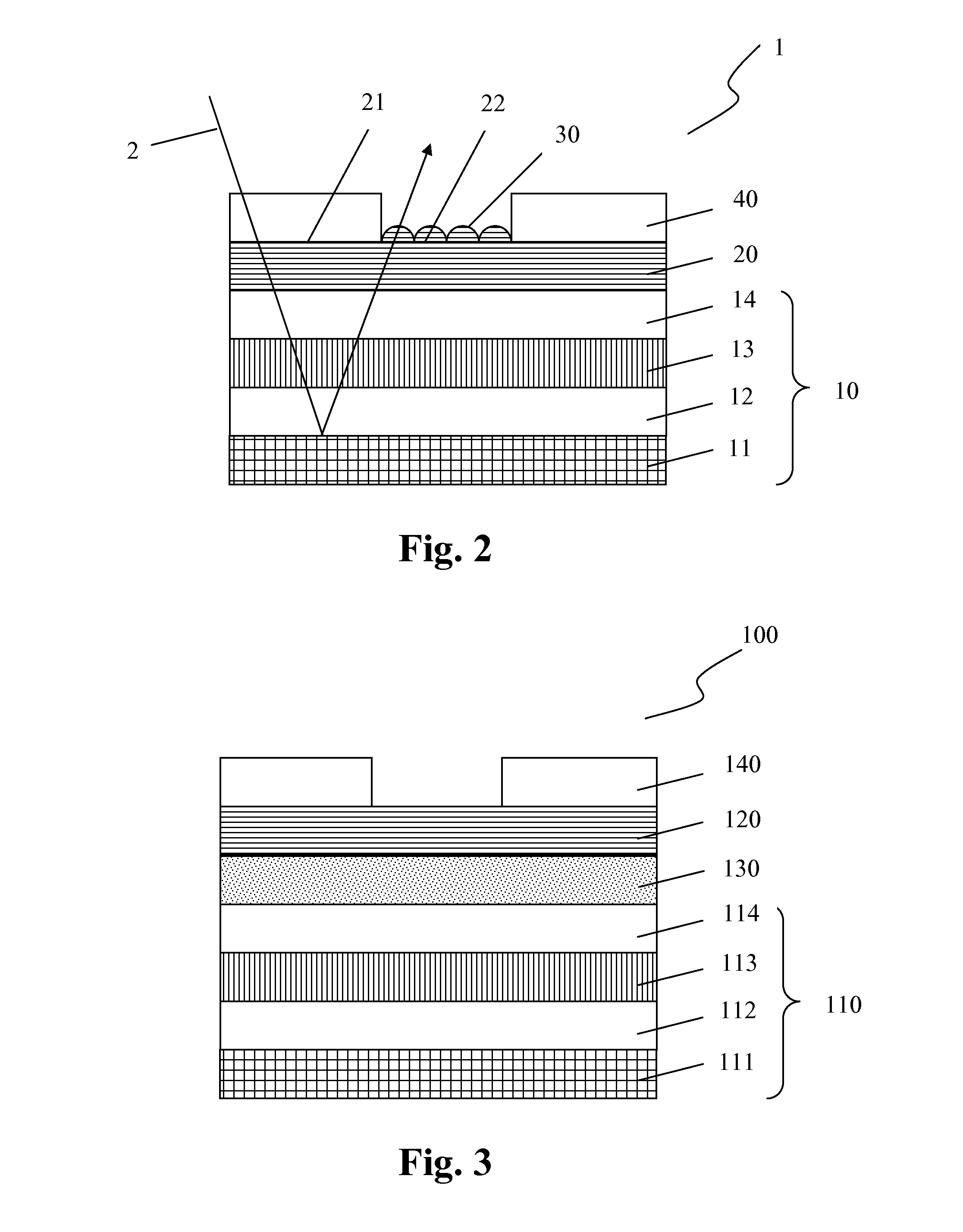
[0040]FIG. 2 schematically shows a light collector 1 comprising an OLED 10 and a luminescent material element 20 arranged thereon. In particular, the luminescent material element is in contact with a transparent cover 14 (e.g. glass, plastic, or thin film encapsulation) of the OLED 10. The OLED further comprises a front electrode 13 which is made of a transparent material so that incident light 2 may pass...


PUM


Abstract

The invention provides a light collector (1) comprising a luminescent material element (20), a discontinuous semi-transparent layer (40) adjacent to a first side of the luminescent material element (20), wherein due to the discontinuity of the semi-transparent layer (40) at least one first portion (21) of the luminescent material element covered by the semi-transparent layer and at least one second portion (21) of the luminescent material element not covered by the semi-transparent layer (40) are formed, and a light generating means (10) arranged at a second side of the luminescent material element (20). Further, a method for concentrating light in a light collector (1) is provided, comprising the following method steps: capturing light from the environment by means of a luminescent material (20), concentrating the light in the luminescent material (20) by means of a semi-transparent layer (40) arranged on the luminescent material (20) and light generating means (10), emitting the light in a pre-determined area (22) of the light collector (1) by means of an out-coupling structure (30) so as to generate a pre-determined light emitting image.

Description

FIELD OF THE INVENTION[0001]The invention relates to a light collector having a luminescent material element, a semi-transparent layer, and a light generating means as e.g. an organic light emitting diode (OLED). Further, a signage panel having a luminescent material and e.g. an OLED is provided as well as a method for concentrating light by capturing, concentrating, and re-emitting the light in and from a light collector.BACKGROUND OF THE INVENTION[0002]Signage systems are for example directional signs in buildings and roads, signs outside of buildings, advertisement boards, information boards etc. and may also be used for decorative purposes. Signage systems provide images with motives as depicted for example in FIG. 1. These signage systems are usually provided with a backlight or are equipped with a side emissive lamp in order to be easier seen by the people passing by.[0003]The lamps functioning as backlights or as side emissive lamps usually emit the light continuously once tu...

Claims


Application Information

Patent Timeline
IPC IPC(8): G09F13/20F21V9/00E01F9/615
CPCG09F13/20F21V9/00F21V9/20G09F13/22G09F2013/225Y02B20/30Y02E10/52
Inventor LIFKA, HERBERTPASVEER, WILLEM FRANKEDE BOER, DIRK KORNELIS GERHARDUS
Owner SIGNIFY HLDG BV
Why Eureka
Try Eureka