Waveguide Busbar

a waveguide and busbar technology, applied in the direction of waveguide type devices, electrical devices, coupling devices, etc., can solve the problems of reducing the length of the waveguide, and reducing the service life of the waveguid

Active Publication Date: 2013-12-19
TESAT SPACECOM
View PDF2 Cites 199 Cited by
  • Summary
  • Abstract
  • Description
  • Claims
  • Application Information

AI Technical Summary

Benefits of technology

[0017]The temperature drift of a waveguide busbar can thus be compensated with the parallel resonators as compensation resonators mounted along the waveguide. The phase lengths of the busbar can be kept constant in this way.
[0018]It is also possible for the waveguide busbar to be used by suitable adjustment mechanisms and / or actuators for adjustable phase relations, for example, as an alternative, to be able to set the phase relation between two input ports at multiple predetermined values.

Problems solved by technology

However, due to the relatively high thermal expansion coefficient of aluminum, unwanted changes in phase relations occur in the waveguide busbar during temperature fluctuations.
This leads to a degradation of filter parameters, which is even worse, the greater the length of the waveguide busbar and the greater the deviation from the temperature for which the waveguide busbar was designed.
Consequently, this degradation is especially critical for multiplexers with a high power and a high channel count, because they combine long waveguide busbars and high temperatures.
However, this method is not usually very suitable for frequencies higher than 13 GHz.
Therefore, the stiffness of the waveguide busbar increases greatly and deformation becomes much more difficult.
The same thing also applies to milled half-shell waveguide busbars in which the half-shell flange provides reinforcement of the waveguide busbar, so that compensation with Invar clamps is impossible.

Method used


Image

  • Waveguide Busbar
  • Waveguide Busbar
  • Waveguide Busbar

Examples


Embodiment Construction

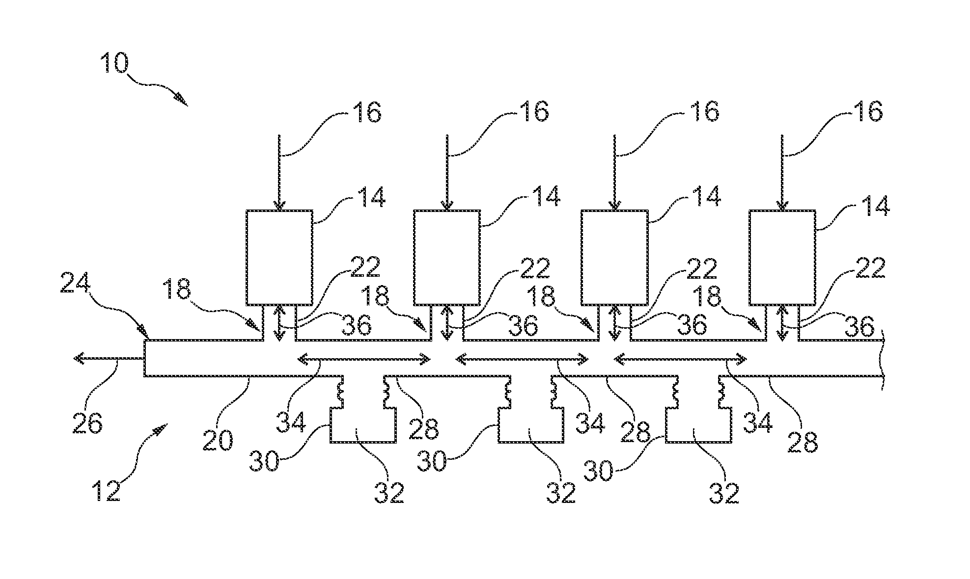
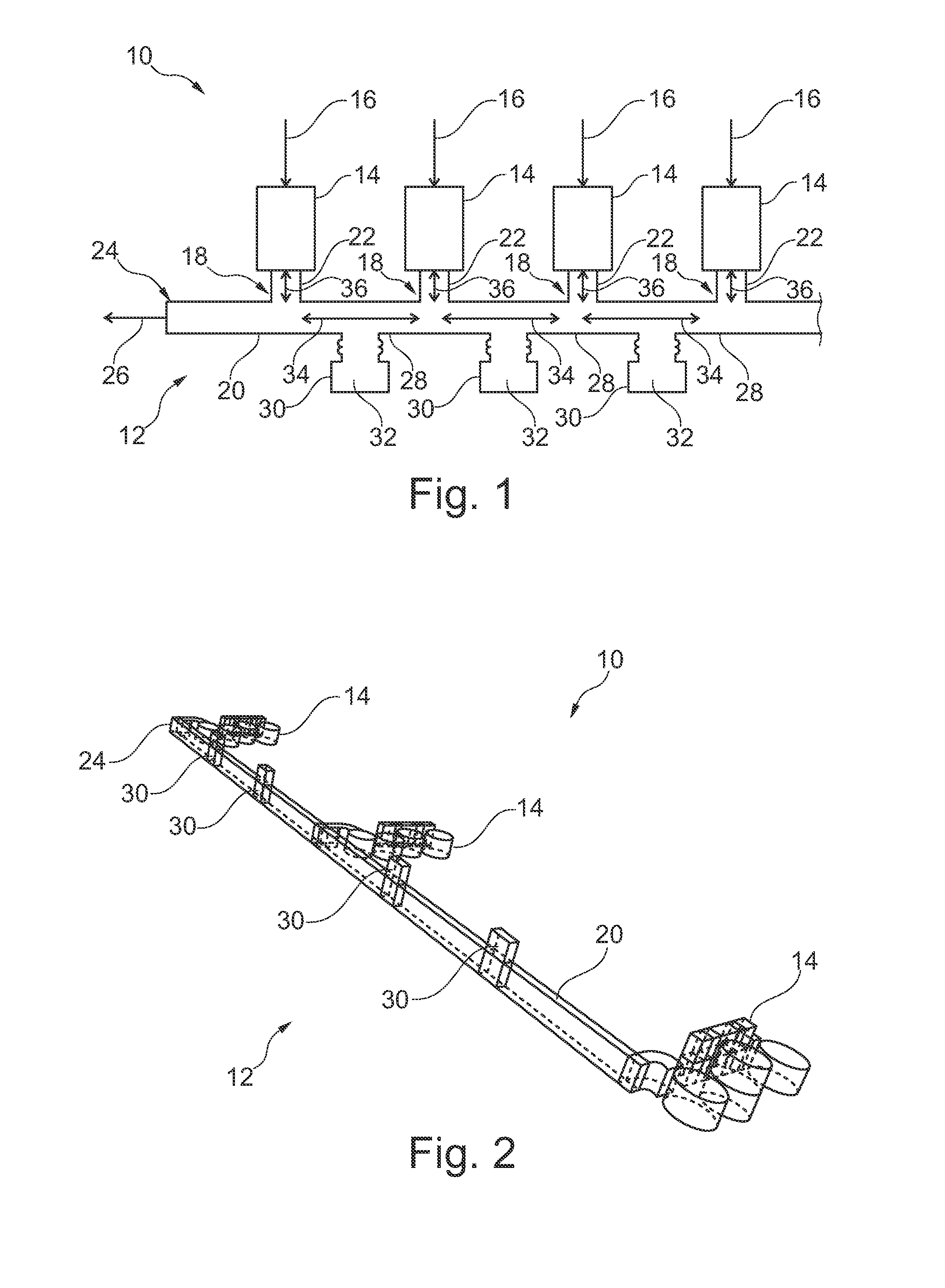
[0053]FIG. 1 shows an output multiplexer 10, which includes a waveguide busbar 12 and a plurality of channel filters 14. High-frequency signals 16 are filtered through the channel filter 14 and are introduced into the waveguide busbar 12 via input ports 18.

[0054]The waveguide busbar 12 comprises a waveguide 20, which has input ports 18 along its direction of extent, these ports being formed in its wall. Connecting pieces 22, which connect the corresponding channel filter 14 to the respective input port 18, are situated between the channel filters 14 and the input ports 18.

[0055]The high-frequency signals 16 generated by the filters travel through the connection pieces 22 and are superimposed on the waveguide 20 and relayed to an output port 24 at the end of the waveguide 20, where an output signal 26 is leaving the waveguide busbar 12.

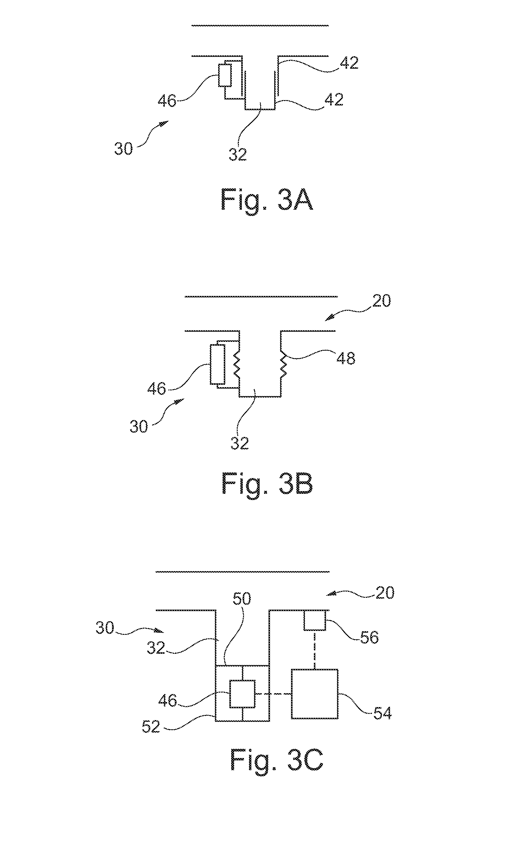
[0056]On each waveguide section 28, each being connected to two neighboring input ports 18, a parallel resonator 30 having a variable volume 32, as in...


PUM


Abstract

A waveguide busbar for converting a plurality of high-frequency input signals into high-frequency output signals, includes a waveguide, a plurality of input ports, which are arranged along the waveguide, such that each input port is intended to receive a high-frequency input signal, an output port on the waveguide for delivering the high-frequency output signal and at least one parallel resonator, which is connected to the waveguide busbar between two input ports. The parallel resonator has a mechanically adjustable volume with which a phase relation of the waveguide is adjustable between the two input ports.

Description

CROSS-REFERENCE TO RELATED APPLICATIONS[0001]The present application claims priority to German Patent Application No. 10 2012 011 765.5, filed Jun. 15, 2012, the entire disclosure of which is herein expressly incorporated by reference.BACKGROUND AND SUMMARY OF THE INVENTION[0002]Exemplary embodiments of the present invention relate to temperature compensation of waveguide busbars for use, for example, in output multiplexers and / or in a communication satellite. Exemplary embodiments of the present invention also relate to a waveguide busbar having adjustable phase relations.[0003]A typical output multiplexer consists of channel filters connected to a waveguide busbar. The high-frequency signals output by the channel filters are combined in the waveguide busbar and output as output signals at one end of the waveguide busbar.[0004]The waveguide busbar is normally designed so that there is the least possible interfering interaction between the channel filters. The phase lengths between ...

Claims


Application Information

Patent Timeline
Patent Type & Authority Applications(United States)
IPC IPC(8): H01P1/213
CPCH01P1/20H01P1/208H01P1/30H01P5/12H01P7/06
Inventor ARNOLD, CHRISTIANPARLEBAS, JEANREICHERTER, DANIEL
Owner TESAT SPACECOM
Why Eureka
Try Eureka