Shaft seal insert

a shaft seal and insert technology, applied in the direction of machines/engines, mechanical apparatus, liquid fuel engines, etc., can solve the problems of higher assembly complexity of these machines, and achieve the effect of reducing the space requirement of the shaft seal insert, simplifying the assembly of such a turbomachine, and reducing the complexity of the turbomachin

Inactive Publication Date: 2014-01-30
SIEMENS AG
View PDF4 Cites 11 Cited by
  • Summary
  • Abstract
  • Description
  • Claims
  • Application Information

AI Technical Summary

Benefits of technology

[0008]Proceeding from the described prior art, the invention addresses the problem of reducing the complexity of a turbomachine having a shaft seal inser...

Problems solved by technology

An arrangement having a dry gas seal and a labyrinth seal is already known from, in each case, DE 10 2009 012 038 A1, DE 42 25 642 C1 a...

Method used


Image

  • Shaft seal insert
  • Shaft seal insert
  • Shaft seal insert

Examples


Embodiment Construction

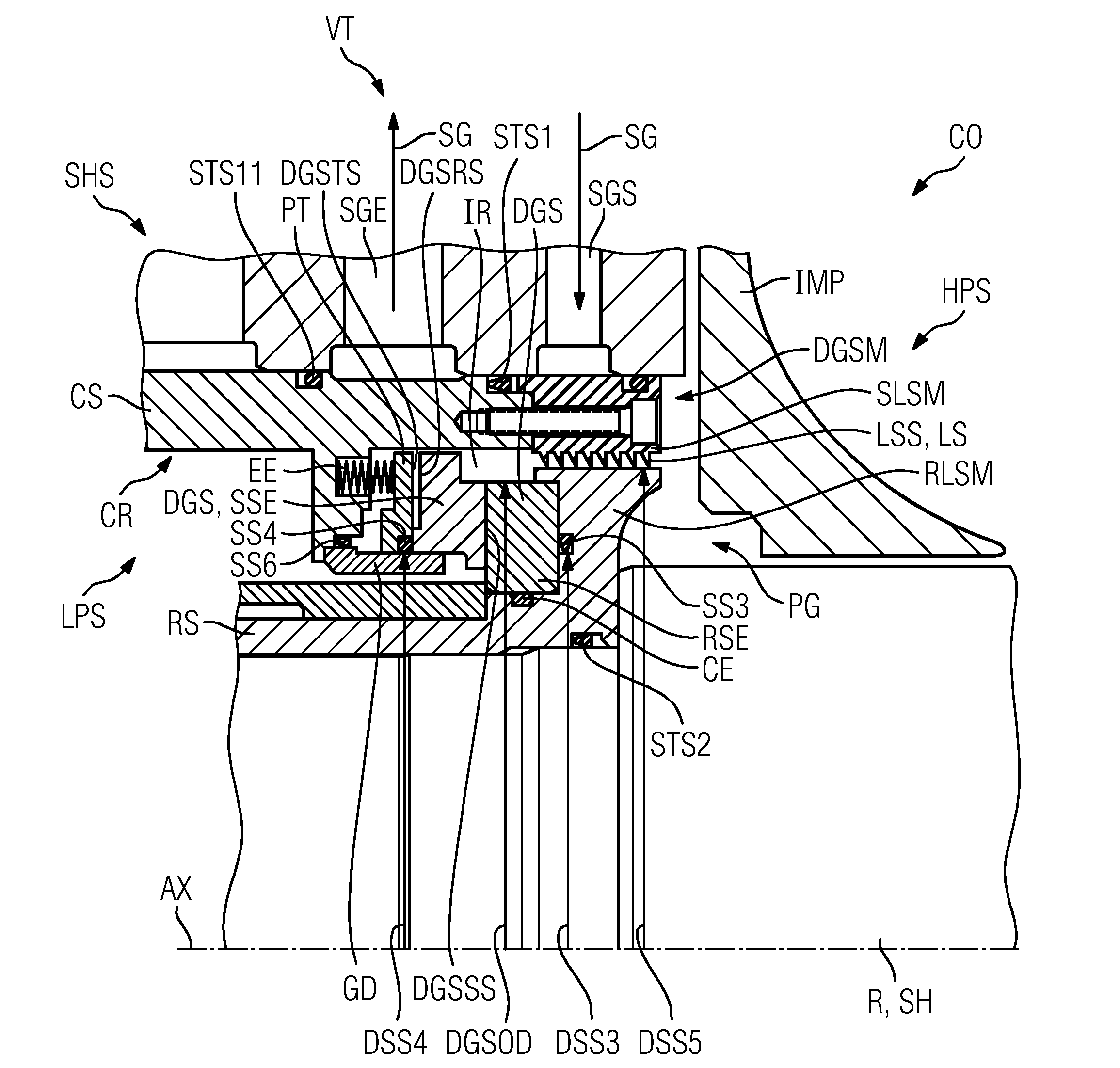
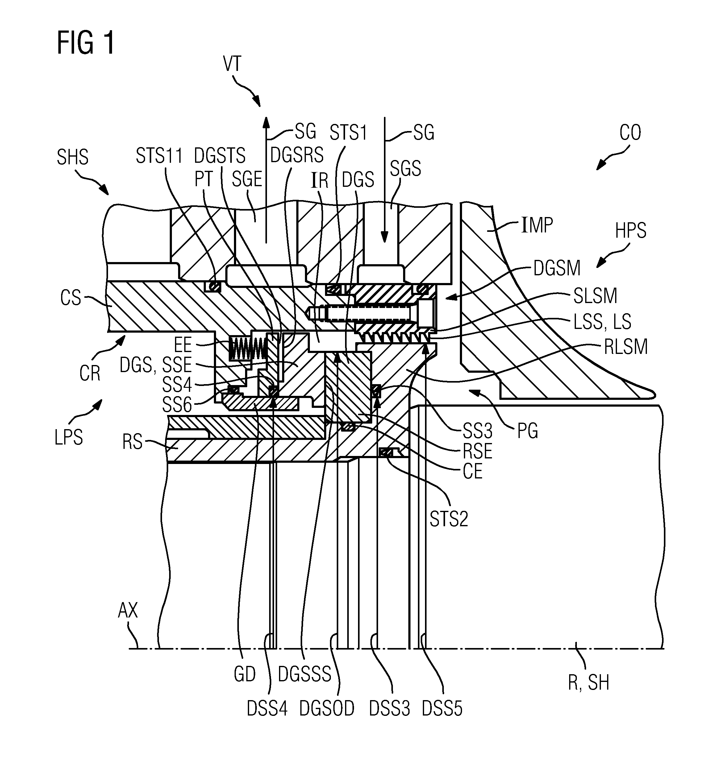
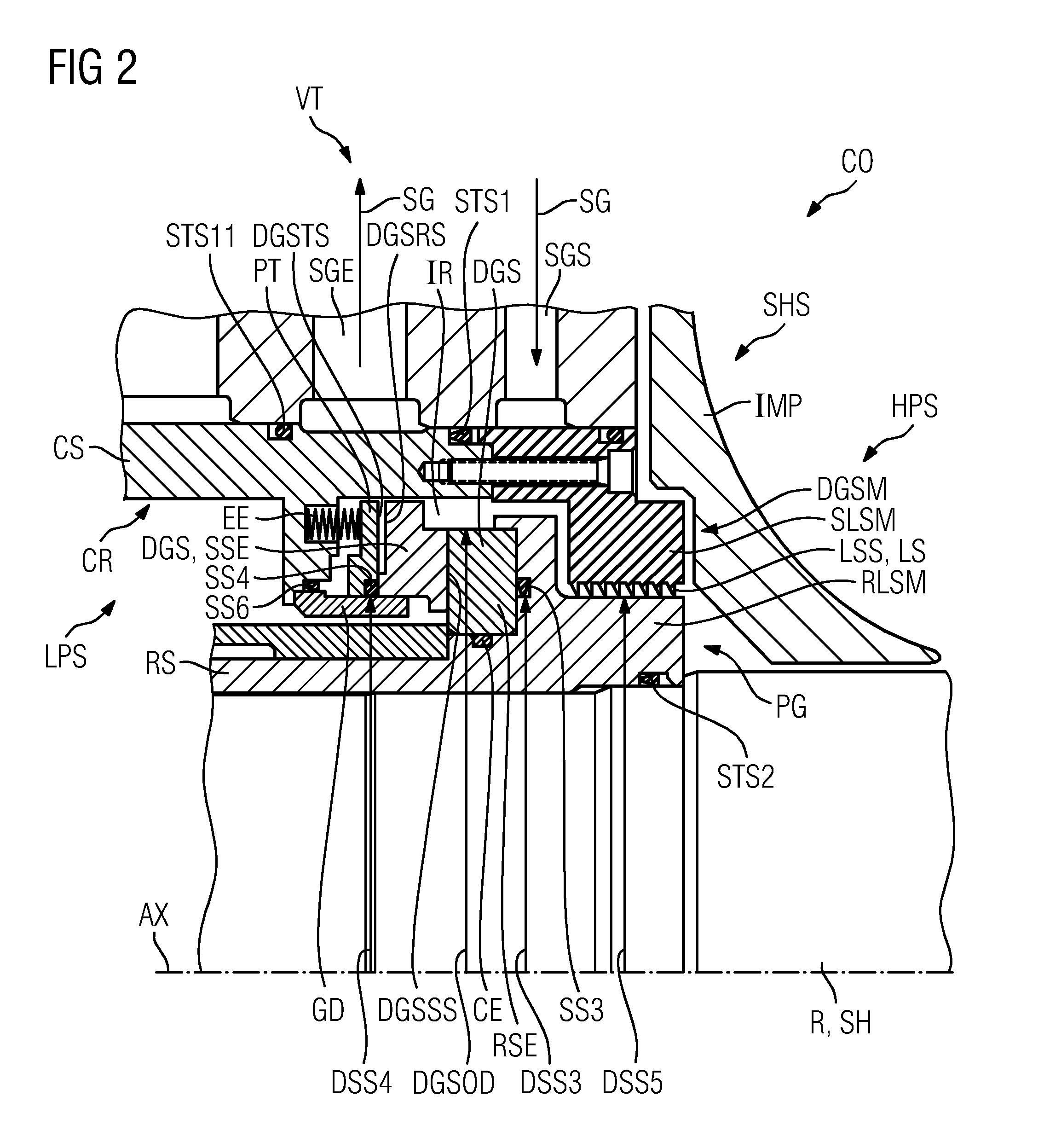
[0028]In the following description, identical components, or components with identical functions, are provided with the same reference sign. Expressions such as axial, radial, circumferential direction, diameter and radius relate to an axis of rotation AX, which is a central axis of a shaft seal insert DGSM according to the invention. The shaft seal insert DGSM illustrated in FIGS. 1 and 2 comprises a stator part CS, a rotor part RS, a dry gas seal DGS and a labyrinth seal LS. The rotor part RS of the shaft seal insert DGSM is mounted in a sealing manner on a shaft SH of a rotor R by means of a second static seal STS2. The shaft SH also bears at least one rotor wheel of a turbomachine CO which, in a manner not illustrated in more detail, is configured as a centrifugal compressor.

[0029]The stator part CS is inserted in a sealing manner into a stator recess CR by means of a first static seal STS1. The first static seal STS1 and the second static seal STS2 have a V-shaped profile arran...


PUM


Abstract

A shaft seal insert for the shaft seal of a turbomachine extending along a rotational axis includes:—a rotor part attachable on a shaft of a rotor,—a stator part insertable into a stator receiving area, and—a dry gas seal having a rotating seal element attached to the rotor part and a fixed seal element attached to the stator part to seal an intermediate space between the two seal elements, which lie opposite each other on a sealing surface extending radially and in the circumferential direction. A labyrinth seal is provided on a high-pressure side in a serial arrangement with the dry gas seal to seal the intermediate space, having a fixed and rotating labyrinth seal parts. The fixed labyrinth seal part is part of the stator part or is fixed thereto. The rotating labyrinth seal part is part of the rotor part or is fixed thereto.

Description

CROSS REFERENCE TO RELATED APPLICATIONS[0001]This application is the US National Stage of International Application No. PCT / EP2012 / 055273, filed Mar. 26, 2012 and claims the benefit thereof. The International Application claims the benefits of German application No. 102011007071.0 DE filed Apr. 8, 2011. All of the applications are incorporated by reference herein in their entirety.FIELD OF INVENTION[0002]The invention relates to a shaft seal insert for a shaft seal of a turbomachine, which extends in an axial direction along an axis of rotation, comprising[0003]a rotor part which is configured such that it can be mounted on a shaft of a rotor which extends along the axis of rotation,[0004]a stator part which is configured such that it can be inserted into a stator recess,[0005]at least one dry gas seal having a rotating sealing element mounted on the rotor part and one static sealing element mounted on the stator part in order to seal an intermediate space between the rotating seali...

Claims


Application Information

Patent Timeline
IPC IPC(8): F01D11/02
CPCF01D11/02F16J15/002F16J15/3464F16J15/40F16J15/44F04D29/124F01D11/003F16J15/447
Inventor MATEMAN, GESINUS
Owner SIEMENS AG
Why Eureka
Try Eureka