Heat exchanger, in particular intercooler

Active Publication Date: 2014-02-27
MAHLE INT GMBH
View PDF17 Cites 12 Cited by
  • Summary
  • Abstract
  • Description
  • Claims
  • Application Information

AI Technical Summary

Benefits of technology

[0012]It is therefore an object of the invention to provide a heat exchanger in which the service life of the heat exchanger is maintained or ca

Problems solved by technology

However, the compression of the air simultaneously entails a significant heating of the same, which is disadvantageous for optimal functioning of the combustion process.
For example, the heating may bring about premature ignition or increased nitrogen oxide emission.
In the conventional art, in the case of reduced tube wall thicknesses or reduced plate thicknesses, the strength of the tube/plate joint is not always ensured, resulting in a redu

Method used


Image

  • Heat exchanger, in particular intercooler
  • Heat exchanger, in particular intercooler
  • Heat exchanger, in particular intercooler

Examples


Embodiment Construction

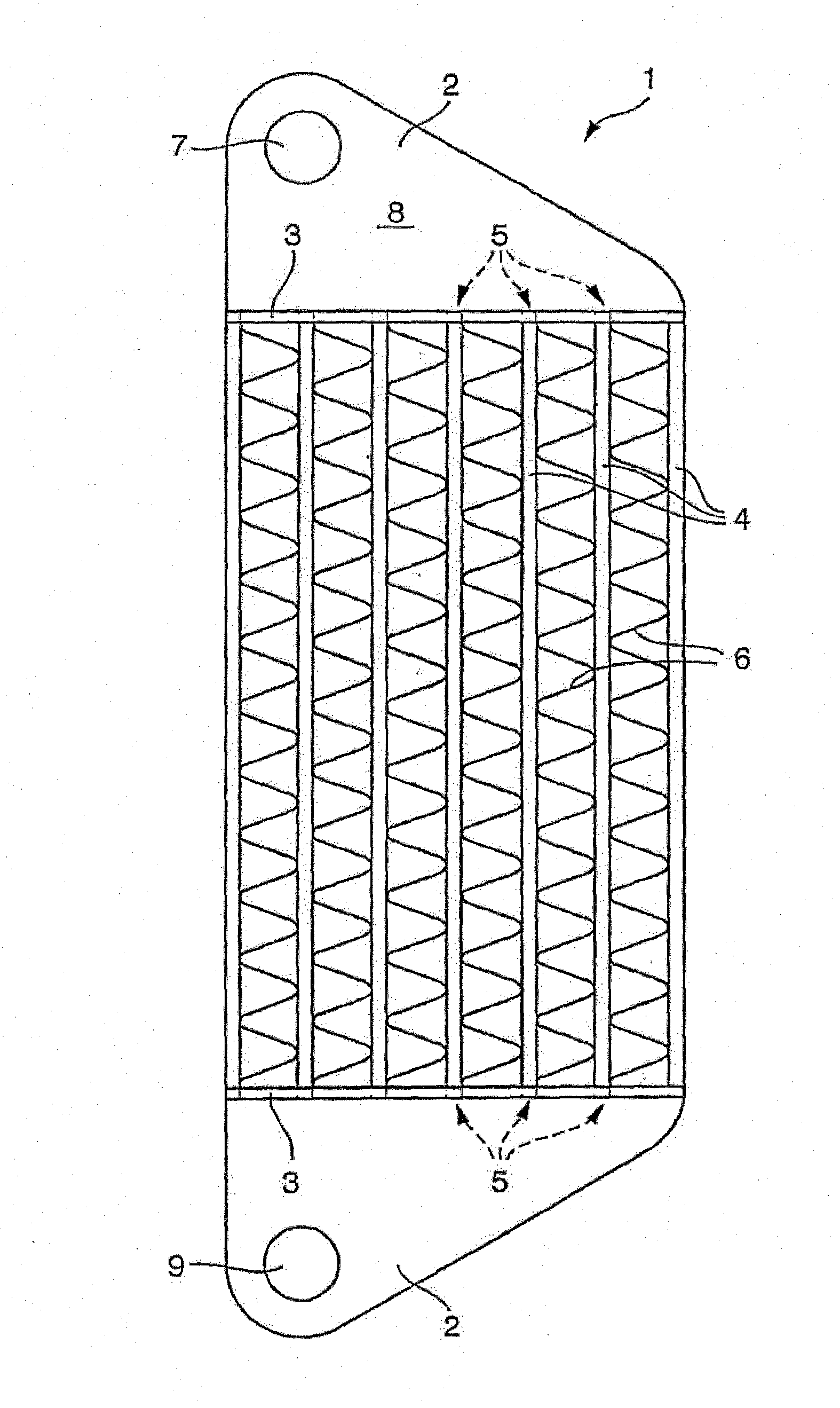
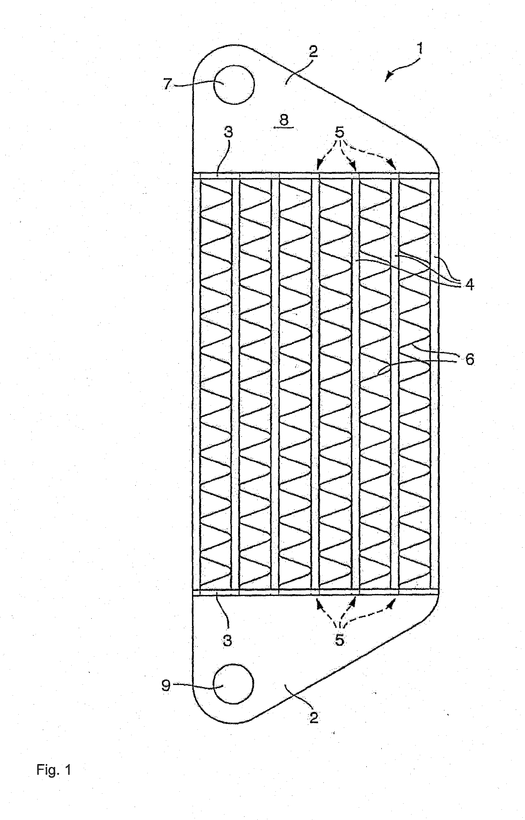
[0031]FIG. 1 shows a heat exchanger 1 that has two opposing header boxes 2, wherein each of the header boxes 2 is provided on one side with an essentially flat, slab-like plate 3. The header boxes 2 here are arranged on the heat exchanger 1 such that their plates 3 face one another and extend parallel to one another. Located between the header boxes 2 or between their plates 3, perpendicular to the plates 3, are tubes 4, preferably flat tubes, that are placed adjacent to one another and extend parallel to one another, and whose ends pass through the plates 3 in openings 5 provided for this purpose, thereby connecting the header boxes 2 in a communicating manner. Cooling ribs 6, which are zigzag shaped, for example, are placed between adjacent tubes 4. The tubes 4 are attached to the header boxes 2 or their plates 3 by soldering.

[0032]When the heat exchanger 1 is designed as an intercooler, the hot air compressed by a turbocharger that is not shown in detail enters an interior 8 of t...


PUM


Abstract

A heat exchanger, in particular an intercooler, is provided that includes at least one collector box that has a base. At least one tube engages into a passage in an approximately perpendicular manner with respect to the base, the passage protruding out of the base and surrounding a tube end, and the passage has a rectangular cross-section that is adapted to the outer circumference of the tube. The aim of the invention is to further extend the service life of the heat exchanger with a further reduction of the wall thickness of the collector box base as well as of the tube. This is achieved in that a wall thickness of the passage is thinned at least in a corner region.

Description

[0001]This nonprovisional application is a continuation of International Application No. PCT / EP2012 / 057982, which was filed on May 2, 2012, and which claims priority to German Patent Application No. 10 2011 075 071.1, which was filed in Germany on May 2, 2011, and which are both herein incorporated by reference.BACKGROUND OF THE INVENTION[0002]1. Field of the Invention[0003]The invention relates to a heat exchanger, in particular an intercooler, comprising at least one header box that has a plate, wherein at least one tube approximately perpendicular to the plate engages a passage that projects out of the plate and surrounds a tube end, wherein the passage has a quasi-rectangular cross-section matched to the outer circumference of the tube.[0004]2. Description of the Background Art[0005]In order to achieve a performance improvement in an internal combustion engine, the air to be delivered for combustion can be compressed, for example with a turbocharger, before it is delivered to th...

Claims


Application Information

Patent Timeline
IPC IPC(8): F28F9/02
CPCF28F9/02F02B29/045F28D1/05366F28D2021/0082F28F9/0246Y02T10/12F28D21/00F28F9/18
Inventor AUGENSTEIN, CLAUSBRONNER, HARALDPOSSET, STEPHANKLIPPHAHN, SILVIA-HELENATYULYUKOVSKIY, EDUARD
Owner MAHLE INT GMBH
Why Eureka
Try Eureka