Communication system, path switching method and communication device

a communication system and path switching technology, applied in the field of communication systems and path switching methods, can solve the problems limited provision of redundant paths, and once-off communication of users, and achieve the effect of adverse effects on communication quality

Inactive Publication Date: 2014-07-03
HITACHI LTD
View PDF3 Cites 17 Cited by
  • Summary
  • Abstract
  • Description
  • Claims
  • Application Information

AI Technical Summary

Benefits of technology

[0011]A technique 1 disclosed in JP-A-2006-311254 provides a redundant path of two communication devices (router) by an optical path. However, since the redundant path is autonomously calculated and set by each communication device after a failure occurs, there arises a problem that a communication quality is adversely affected when a plurality of pa

Problems solved by technology

However, since the redundant path is autonomously calculated and set by each communication device after a failure occurs, there arises a problem that a communication quality is adversely affected when a plurality of paths is unevenly set for a certain communication node.
Also, there arises such a problem that the provision of the redundant path is limited within one communication protocol, and

Method used


Image

  • Communication system, path switching method and communication device
  • Communication system, path switching method and communication device
  • Communication system, path switching method and communication device

Examples


first embodiment

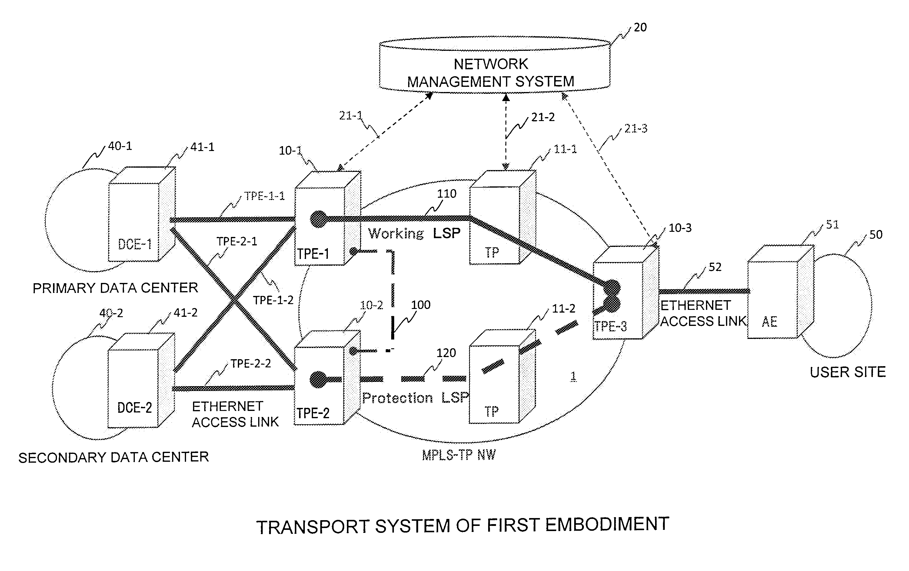
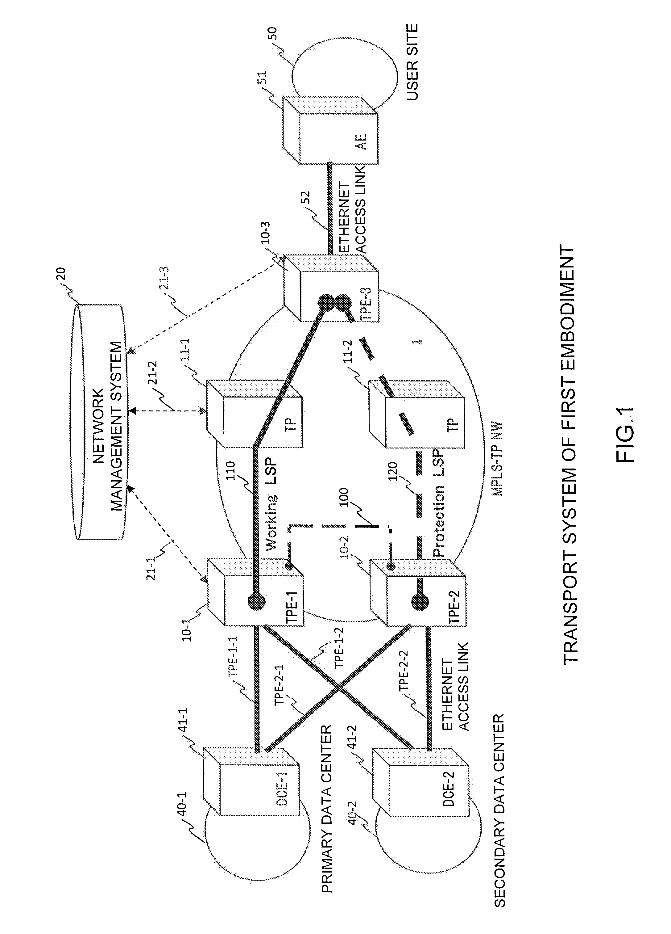
[0057]Hereinafter, a first embodiment of the present invention will be described in detail with reference to the accompanying drawings. In this embodiment, an example in which a multi-protocol label switching-transport profile (MPLS-TP) is used for a communication protocol of a packet transport NW will be described. However, other communication protocols are applicable, and the same effects are obtained without depending on the communication protocol of a packet transport network. Also, an example in which the Ethernet is used for the access link, and a link aggregation is used for redundancy of an Ethernet access link will be described. An appropriate communication protocol that can make the access links redundant is used as the access links with the same effects.

[0058]FIG. 1 is a diagram illustrating an example of a packet transport system in which a primary data center 40-1, a secondary data center 40-2, and a user site 50 are connected to a packet transport network (hereinafter ...

second embodiment

[0195]Hereinafter, a second embodiment of the present invention will be described in detail with reference to the accompanying drawings.

[0196]FIG. 13 is a diagram illustrating a network system configured by a packet transport device according to a second embodiment. In the second embodiment, a P-P (primary node-primary)-LSP 110, and a P-S (primary node-secondary)-LSP 210 are set between a TPE-1 node 400-1 and a TPE-3 node 400-3. Also, an S-P (secondary node-primary)-LSP 120, and an S-S (secondary node-secondary)-LSP 220 are set between a TPE-2 node 400-2 and the TPE-3 node 400-3. In this way, the LSPs are doubled between the respective TPE nodes. In the drawings, one solid among those four lines is prepared as an LSP of operation (ACT), and the remaining three dashed line LSPs are prepared as LSPs of standby (SBY) when a failure occurs. In this embodiment, both of the LSP between the TPE-1 node 400-1 and the TPE-3 node 400-3, and the LSP between the TPE-2 node 400-2 and the TPE-3 no...


PUM


Abstract

When a communication path between a user site and a dual-homed data center is made redundant, a communication between the user site and a server within a data center can be continued. An edge node DCE-1 of a data center 40-1 and edge nodes TPE-1, TPE-2 of a transport network are connected to each other by a link TPE-1-1 and a link TPE-2-1, respectively. The edge nodes TPE-3 and TPE-1, TPE-2 that hold a node AE51 of a user site 50 are set with an LSP 110 of an active system, and an LSP 120 of a backup system, respectively. One of the links is active, and the other link is backup, and the LSP of the TPE node having the active link in the LSP 100 and the LSP 120 is made active. The respective links are prioritized, and the links are switched to an active state in order from the links higher in the order of priority when a link failure or an LSP failure occurs.

Description

CLAIM OF PRIORITY[0001]The present application claims priority from Japanese patent application JP 2012-286938 filed on Dec. 28, 2012, the content of which is hereby incorporated by reference into this application.BACKGROUND OF THE INVENTION[0002]1. Field of the Invention[0003]The present invention relates to a communication system, a path switching method, and a communication device, and more particularly to a communication system, a path switching method, and a communication device which provide an end-to-end redundant path of a communication path in an environment in which two or more kinds of redundant protocols are mixed together.[0004]2. Description of the Background Art[0005]IT service providing configurations using a communication network represented by a cloud service are increased. Since a service use response and continuity is important in an IT service using this communication network, a high quality and a high reliability are demanded for the communication network.[0006...

Claims


Application Information

Patent Timeline
IPC IPC(8): H04L12/703H04L12/707H04L12/725H04L45/247H04L45/28H04L45/24H04L45/58H04L45/586
CPCH04L45/28H04L45/30H04L45/22H04L45/58
Inventor TAKASE, MASAYUKIENDO, HIDEKIASHI, YOSHIHIROUETA, TAISUKE
Owner HITACHI LTD
Why Eureka
Try Eureka