elevator

a technology of elevators and cables, applied in the field of elevators, can solve the problems of compromising, increasing the workload of elevators, etc., and achieves the effects of good longitudinal force transmission capability of roping, good maximum load of elevators, and space efficien

Active Publication Date: 2014-08-14
KONE CORP
View PDF29 Cites 6 Cited by
  • Summary
  • Abstract
  • Description
  • Claims
  • Application Information

AI Technical Summary

Benefits of technology

[0004]It is brought forward a new elevator, which comprises a hoistway, an elevator car and a counterweight vertically movable in the hoistway, a drive machine comprising a drive sheave, a roping comprising one or more ropes between the elevator car and the counterweight and passing around the drive sheave and suspending the elevator car and the counterweight, wherein the drive sheave is positioned in the hoistway space which is between a hoistway wall and the vertical projection of the car the drive sheave rotation plane being at least substantially parallel to the hoistway wall. Said rope(s) is / are belt-like, each comprising one force transmission part or a plurality of force transmission parts for transmitting force in the longitudinal direction of the rope, which force transmission part(s) is / are made of composite material comprising reinforcing fibers in a polymer matrix, an in that the reinforcing fibers are carbon fibers, and in that said one force transmission part or each of said plurality of force transmission parts has width larger than thickness thereof as measured in width-direction of the rope. In this way a very space efficient elevator is achieved. In particular, the cross section of individual ropes and the overall space required by the rope bundle and the drive sheave are effectively utilized. Furthermore, also the longitudinal force transmission capabilities of the roping are good. In this way the elevator maximal load is good despite the very compact hoisting function.

Problems solved by technology

In this type of elevators the problem is that the hoisting function, i.e. the drive machine, the counterweight and the roping and other related components, must be fitted so that a great number of various preferences are met at the same time.
Many of the requirements for an elevator affect each other and compromising is necessary.
When the elevator is to be made machine-roomless the space requirements become especially challenging.
Especially, the size of the machinery and the size of the rope bundle passing back and forth in the hoistway consumes some room between the car and the hoistway wall.

Method used


Image

  • elevator
  • elevator
  • elevator

Examples


Embodiment Construction

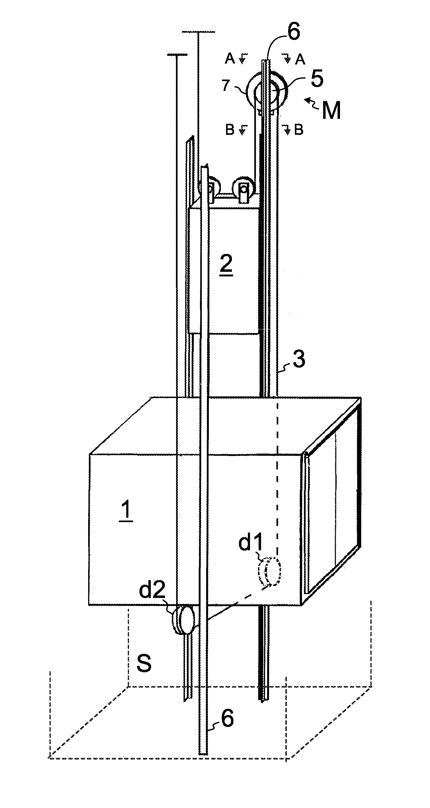
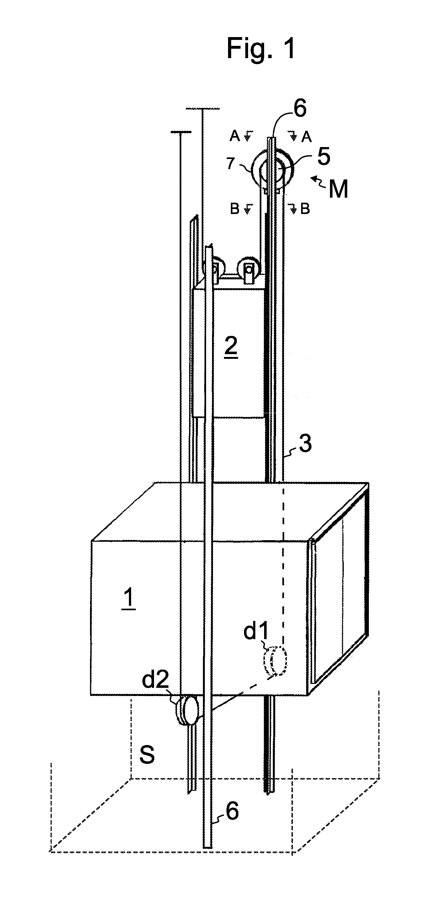
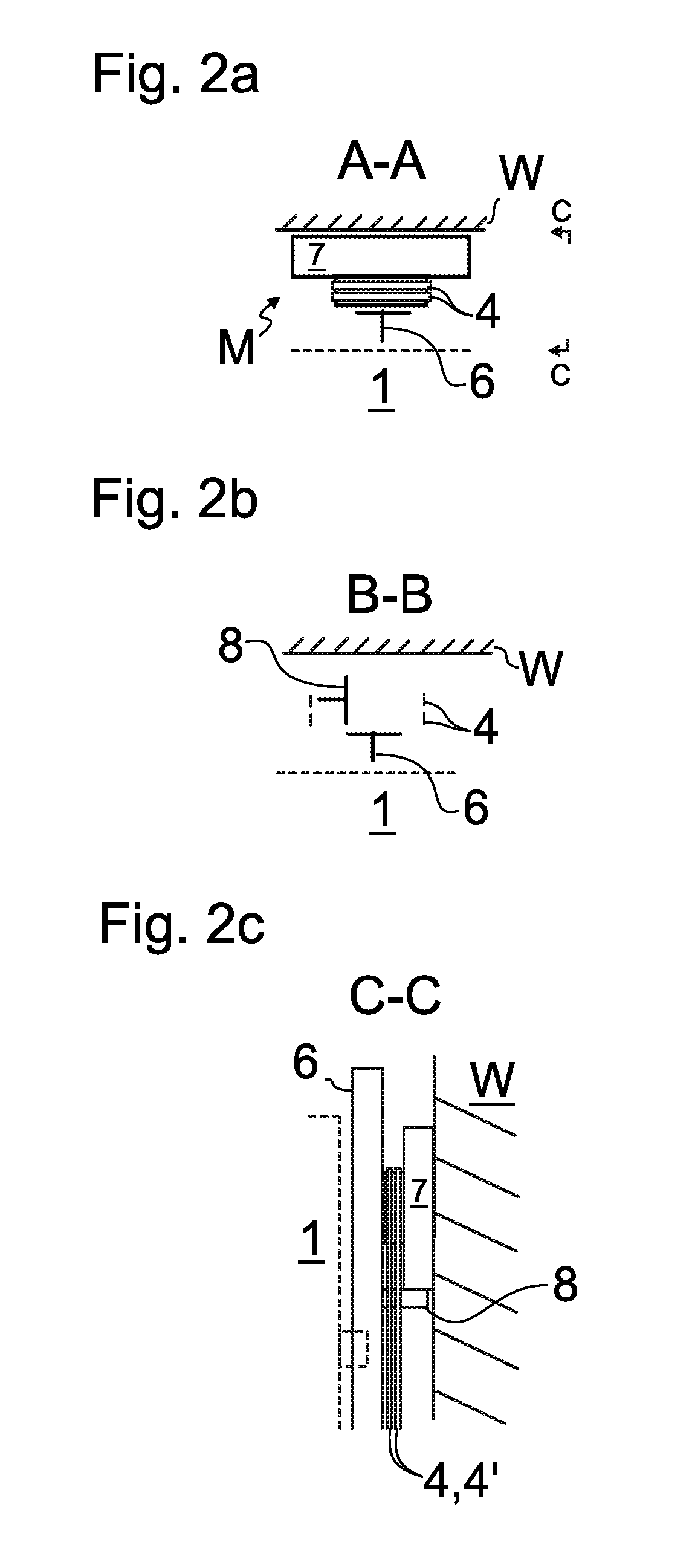
[0031]FIGS. 1 and 2 illustrate an elevator according to a preferred embodiment. The elevator comprises a hoistway S, an elevator car 1 and a counterweight 2 vertically movable in the hoistway S, and a drive machine M which drives the elevator car under control of an elevator control system (not shown). The drive machine M is located in the top part of the hoistway S. It comprises a motor 7 and a drive sheave 5 engaging an elevator roping 3, which is connected to the car 1. Thus, driving force can be transmitted from the motor to the car 1 via the drive sheave 5 and the roping 3. The roping 3 passes around the drive sheave 5 and suspends the elevator car 1 and the counterweight 2 and comprises ropes 4,4′ connecting the elevator car 1 and the counterweight 2. The drive sheave 5 is positioned in the hoistway space which is between the hoistway wall W and the vertical projection of the car 1 the drive sheave rotation plane being parallel to the hoistway wall W. In this way the drive she...


PUM


Abstract

An elevator includes a hoistway, an elevator car and a counterweight vertically movable in the hoistway, a drive machine including a drive sheave, a roping including one or more ropes between the elevator car and the counterweight and passing around the drive sheave and suspending the elevator car and the counterweight. The drive sheave is positioned in the hoistway space between a hoistway wall and the vertical projection of the car, the drive sheave rotation plane being at least substantially parallel to the hoistway wall. The rope(s) is/are belt-like, each including at least one force transmission parts for transmitting force in the longitudinal direction of the rope, which force transmission part is made of composite material including reinforcing fibers in a polymer matrix. The reinforcing fibers are carbon fibers, and the force transmission part has width larger than thickness thereof as measured in width-direction of the rope.

Description

FIELD OF THE INVENTION[0001]The invention relates to an elevator. The elevator is particularly meant for transporting passengers and / or goods.BACKGROUND OF THE INVENTION[0002]Modern elevators usually have a drive machine which drives the elevator car under control of an elevator control system. The drive machine typically comprises a motor and a drive sheave engaging an elevator roping which is connected to the car. Thus, the driving force is transmitted from the motor to the car via the roping. There are elevators which do not have a special machine room for accommodating the drive machine. These elevators may be of the type where the drive machine is positioned in the elevator hoistway, i.e. to the same space where the elevator car and possibly also the counterweight of the elevator moves. In this type of elevators the problem is that the hoisting function, i.e. the drive machine, the counterweight and the roping and other related components, must be fitted so that a great number ...

Claims


Application Information

Patent Timeline
Patent Type & Authority Applications(United States)
IPC IPC(8): B66B7/06B66B7/02B66B11/04B66B11/00
CPCB66B7/062B66B7/02B66B11/043B66B11/008B66B11/0045
Inventor VALJUS, PETTERIPELTO-HUIKKO, RAIMOLAMPINEN, RIKU
Owner KONE CORP
Why Eureka
Try Eureka