Lens driving device with image stablilizer function

a driving device and lens technology, applied in the direction of dynamo-electric components, dynamo-electric machines, instruments, etc., can solve the problems of increasing power consumption, increasing parts or assembling costs, etc., and achieve the effect of efficient generation of swinging thrust for

Active Publication Date: 2014-12-25
HUIZHOU SAGETECH OPTRONICS CO LTD
View PDF3 Cites 20 Cited by
  • Summary
  • Abstract
  • Description
  • Claims
  • Application Information

AI Technical Summary

Benefits of technology

[0010]The object of the present invention is to provide an improved lens driving device with image stabilizer function, the lens driving device has a light-weight swing part for realizing image stabilizer function and can efficiently generate swinging thrust force thus there is no need of off-centering correction assembly.

Problems solved by technology

Therefore, an additional part or an additional control circuit for generating the correcting current is needed to be set in the lens driving device 600, thus the lens driving device 600 is in large size, the part cost or assembling cost is increased, and the power consumption is further increased.

Method used


Image

  • Lens driving device with image stablilizer function
  • Lens driving device with image stablilizer function
  • Lens driving device with image stablilizer function

Examples


embodiment i

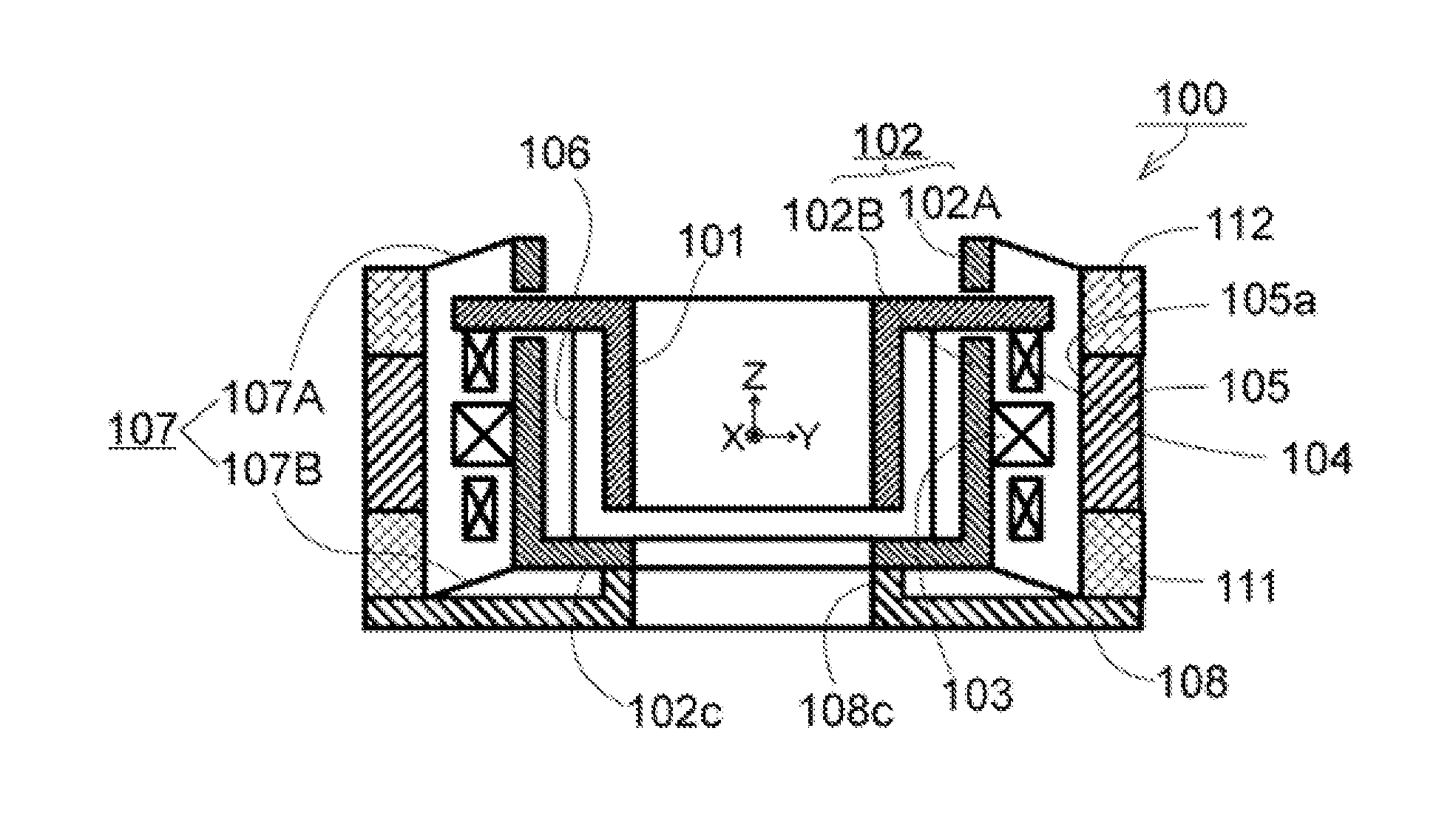
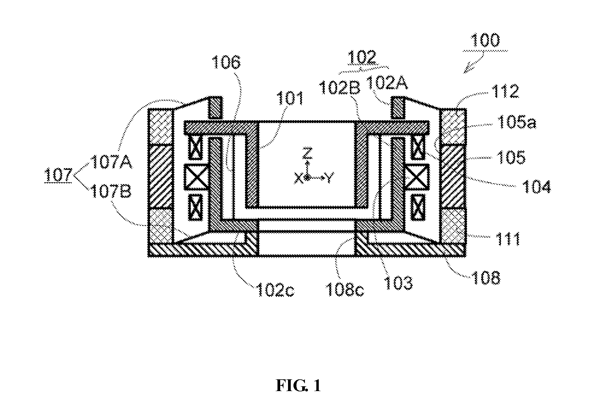
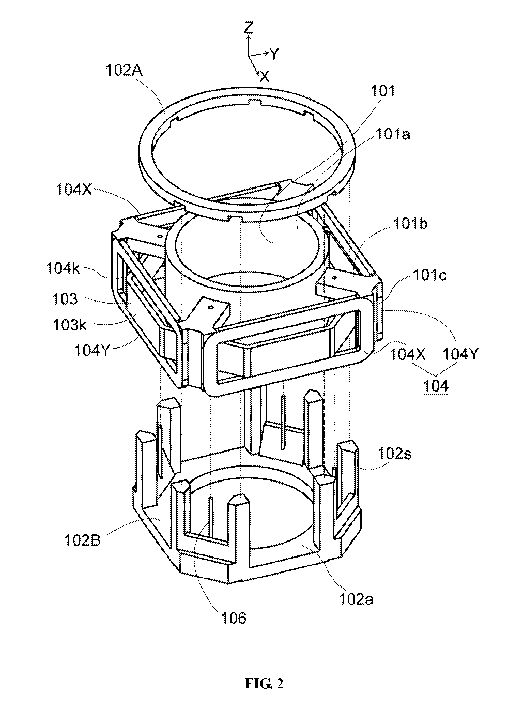
[0044]FIG. 1 is a longitudinal cross-section view of a lens driving device 100 with image stabilizer function according to a first embodiment of the present invention. FIG. 2 is an exploded view of a main part of a swing suspension of the lens driving device 100 according to the first embodiment of the present invention. FIG. 3 is a perspective view of a main part illustrating the position relationship between the permanent magnets and the second coils for swinging the lens (not shown) as well as the first coil(s) for moving the lens. FIG. 4 is a cutoff view illustrating magnetic loops utilizing the permanent magnet and the magnet yoke. FIG. 5 is a perspective view illustrating the suspension utilizing a first spring component for moving the lens. Moreover, FIG. 6 is whole exploded view of the lens driving device 100 according to the first embodiment of the present invention.

[0045]To clearly describe the present invention, the optical axis of the unshown lens is defined as Z axis of...

embodiment ii

[0114]FIG. 12 is a longitudinal cross-section view of a lens driving device 500 with image stabilizer function according to the second embodiment of the present invention. FIG. 13 is a perspective view of a main part of a swing suspension of the lens driving device with image stabilizer function according to the second embodiment, and FIG. 14 is a perspective view of a main part of position relationship among the permanent magnet, the first coil for moving the lens and the second coils for swinging the lens. FIG. 15 is a perspective view of a magnetic loop utilizing the permanent magnet and the magnet yoke. FIG. 16 is an exploded view of the suspension utilizing the first spring component. FIG. 17 is an integral decomposition perspective view of the lens driving device 500 with image stabilizer function according to the second embodiment of the present invention. Moreover, FIG. 14 is shown through section view by partly cutting the second coil 504 for the purpose that the front side...


PUM


Abstract

The present invention provides a lens driving device with image stabilizer function with high driving efficiency of second coils for swinging the lens, and the swing part is light. A lens support accommodating the first coil wound around the Z axis, and a base are respectively connected with first spring components extending along the direction perpendicular to the Z direction. The second coils are wound around the X direction and the Y direction and configured on the outer side of the first coil. A lens carrier and a carrier bracket provided with the second coils are connected with the second spring component extending along the Z direction. The second spring component is supported by the lens carrier and can swing in the X direction and the Y direction.

Description

BACKGROUND OF THE INVENTION[0001]1. Field of the Invention[0002]The present invention relates to a lens driving device used in a camera such as a portable phone, and in particular to a lens driving device with image stabilizer function.[0003]2. Description of Related Art[0004]Many cameras on sale have an image stabilizer function. An object is focused by moving a lens disposed in the camera forwards or backwards relative to the object to be shot, and meanwhile the lens is swung in a direction perpendicular to the shooting direction of the lens, thus blur flow of the image imaged on an image sensor is inhibited. For example, Japan patent application JP 2011-65140 discloses a lens driving device for auto focus which is suspended supported in the Z direction, the lens driving device can swing in X direction and Y direction relative to a base.[0005]As shown in FIGS. 21A and 21B, in the lens driving device 600 with image stabilizer function, a structure for enabling the lens driving devi...

Claims


Application Information

Patent Timeline
Patent Type & Authority Applications(United States)
IPC IPC(8): G02B27/64
CPCG02B27/646H02K41/0356
Inventor TERAJIMA, KOKICHI
Owner HUIZHOU SAGETECH OPTRONICS CO LTD
Why Eureka
Try Eureka