Magnetic resonance imaging device and RF coil

a magnetic resonance imaging and coil technology, applied in the direction of reradiation, measurement using nmr, instruments, etc., can solve the problems of high labor intensity, limited range from which high image quality can be obtained, and the inability to perform simultaneous imaging, etc., to achieve good installation and operability, the effect of low cos

Active Publication Date: 2015-01-29
FUJIFILM HEALTHCARE CORP
View PDF2 Cites 8 Cited by
  • Summary
  • Abstract
  • Description
  • Claims
  • Application Information

AI Technical Summary

Benefits of technology

[0014]The present invention realizes a portable table which can be attached to and detached from a gantry, enables high-resolution imaging of a head and a neck and high-speed imaging of a whole body both in Head-First mode and Feet-First mode, and is provided with an RF coil system with good installability and operability, and an MRI device including that portable table at relatively low cost.

Problems solved by technology

A range in which simultaneous imaging can be performed is limited to the static magnetic field space at maximum, and a range from which a high image quality can be obtained is limited to a sensitivity range of the RF reception coil.
However, since the integrated RF coil is heavy, there is a problem that a lot of labor is required for detachment.

Method used


Image

  • Magnetic resonance imaging device and RF coil
  • Magnetic resonance imaging device and RF coil
  • Magnetic resonance imaging device and RF coil

Examples


example 1

[0029]The best mode of the present invention is described below as a first example of the present invention, referring to FIGS. 1 to 6 and FIG. 13.

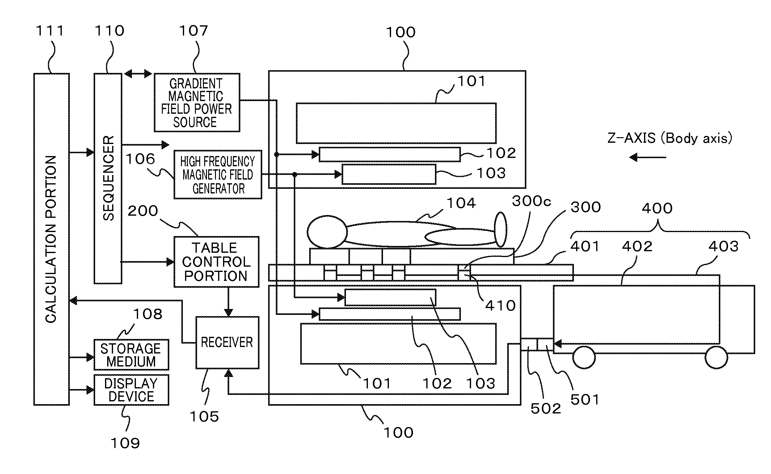
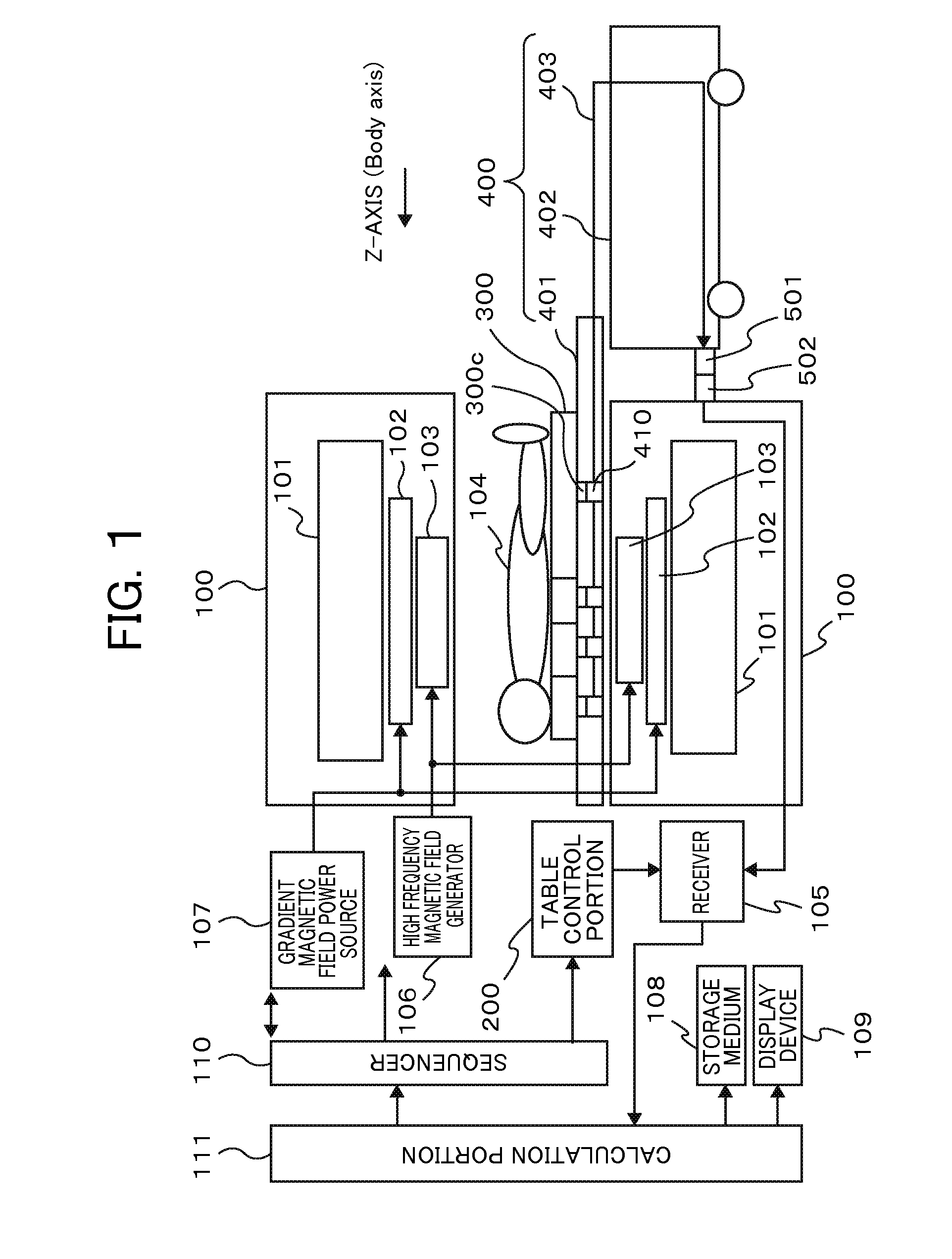
[0030]FIG. 1 is a diagram showing an entire magnetic resonance imaging device of the present invention, and is an exemplary structure diagram of an MRI device having a portable table 400 which can be attached to and detached from a gantry 100. As shown in FIG. 1, the gantry 100 of the MRI device in the present invention includes a magnet 101 which generates a static magnetic field, a gradient magnetic field generation coil 102 which generates a gradient magnetic field, and a high frequency transmitter coil 103 which generates a high frequency magnetic field.

[0031]The portable table 400 which can be attached to and detached from the gantry 100 by docking connectors 501 and 502 includes a table top 401 which can move in z-axis direction on a frame 402, and wired composite cable wiring 403. On or in the table top 401, an RF coil 300 is provi...

example 2

[0061]A second example of the present invention is described below, referring to FIG. 1 and FIG. 7. In this example, an example of division and installation of RF coil units is described which enables the RF coil units to be arranged not only in the longitudinal direction of the table top 401 but also in the lateral direction (body width direction).

[0062]FIG. 7 is a structure diagram showing a third RF coil unit 303, a second RF coil unit 302′, and a sixth RF coil unit 309 in the lateral direction (body width direction) of a table top 401 of a portable table in an MRI device having the portable table 400 which can be attached to and detached from a gantry 100, and shows an exemplary internal structure. In the RF coil unit 300 of the MRI device of FIG. 1, FIG. 4 shows an example in which division of the RF coil unit is made in the body axis direction. This example is different from that example in that division is made in the lateral (body width) direction of the table top.

[0063]For ...

example 3

[0068]A third example of the present invention is described below, referring to FIGS. 1, 8, 9, and 10. In this example, an example of installation in which the divided RF coil units are arranged in a matrix on the table top 401, an exemplary arrangement of table top connectors provided in the table top 401, and an identification structure for installing the respective coil units at correct installation positions are described.

[0069]Example 1 is characteristic in that the adjacent RF coil units in the body axis direction overlap each other such that the end portion of the RF coil unit closer to the center portion of the table top 401 is arranged on the lower side and the end portion of the RF coil unit farther from the center portion of the table top 401 is arranged on the upper side, and Example 2 is characteristic in that the RF coil units adjacent in the body width direction overlap each other in the same manner as that in Example 1. This example shown in the upper diagram of FIG....


PUM


Abstract

A lower cost MRI device with a portable table detachable from the gantry is provided along with a lower cost table equipped with an easy-to-use and easy-to-install RF coil system able to perform high-resolution head and neck imaging and high-speed whole body imaging in both head-first and feet-first modes. This magnetic resonance imaging device has a portable table detachable from the gantry, and the portable table has a docking connector that can be connected to the gantry and a ceiling panel on which an RF coil can be installed to receive nuclear magnetic resonance signals generated by the examinee and to irradiate the examinee with a high-frequency magnetic field. The RF coil is divided into two or more RF coil units, the ceiling panel has a plurality of ceiling panel connectors enabling each RF coil unit to be connected, and each RF coil unit has a connector. Each RF coil unit is arranged in overlapping fashion on the ceiling plate and the ceiling panel connectors and coil connectors are connected without having to establish an electrical connection between RF coil units.

Description

TECHNICAL FIELD[0001]The present invention relates to a magnetic resonance imaging device (MRI device), and relates to a radiofrequency coil (RF coil) used on a portable table.BACKGROUND ART[0002]An MRI device is a device which arranges a subject in a uniform static magnetic field space in a shield room, applies a gradient magnetic field and an exciting high frequency magnetic field, receives a magnetic resonance signal generated by using nuclear magnetic resonance with a high frequency coil (RF reception coil), and images an object to be examined. A range in which simultaneous imaging can be performed is limited to the static magnetic field space at maximum, and a range from which a high image quality can be obtained is limited to a sensitivity range of the RF reception coil.[0003]The performances demanded for the RF reception coil include an S / N ratio which determines whether image quality is good or not, the sensitivity range which determines a field of view of an image, and a pa...

Claims


Application Information

Patent Timeline
Patent Type & Authority Applications(United States)
IPC IPC(8): G01R33/34G01R33/48G01R33/385
CPCG01R33/34092G01R33/48G01R33/385G01R33/3415G01R33/3621G01R33/3657G01R33/34007
Inventor DOHATA, MASAYOSHISOUTOME, YOSHIHISA
Owner FUJIFILM HEALTHCARE CORP
Why Eureka
Try Eureka