RF device and method with improved active load modulation capability

Active Publication Date: 2015-01-29
NXP BV
View PDF5 Cites 6 Cited by
  • Summary
  • Abstract
  • Description
  • Claims
  • Application Information

AI Technical Summary

Benefits of technology

The invention in this patent text aims to optimize the resonance frequency and Q-factor of a resonance circuit for both transmission and reception modes. By adjusting the resistance of an adjustable resistive circuit, the Q- factor can alternate between a higher value and a lower value. This allows for efficient transmission and prevents voltage settling at the antenna network. The invention can be easily integrated into existing RF device designs with minimal hardware modifications and provides a matching pair for RF devices and reader / writer devices.

Problems solved by technology

However, such an antenna configuration is usually not ideal for use in the receiving mode, as the shape of the reader modulation may experience a negative impact.
Similarly, an antenna configuration optimized for the receiving mode is usually not ideal for use in the transmitting mode.

Method used


Image

  • RF device and method with improved active load modulation capability
  • RF device and method with improved active load modulation capability
  • RF device and method with improved active load modulation capability

Examples


Embodiment Construction

[0039]The illustration in the drawing is schematic. It is noted that in different figures, similar or identical elements are provided with the same reference signs or with reference signs, which differ only within the first digit.

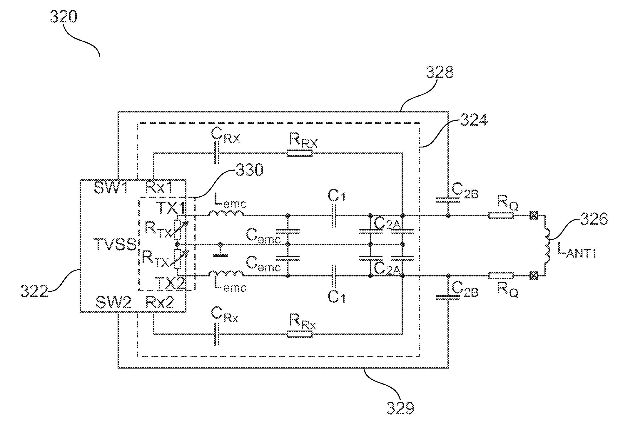
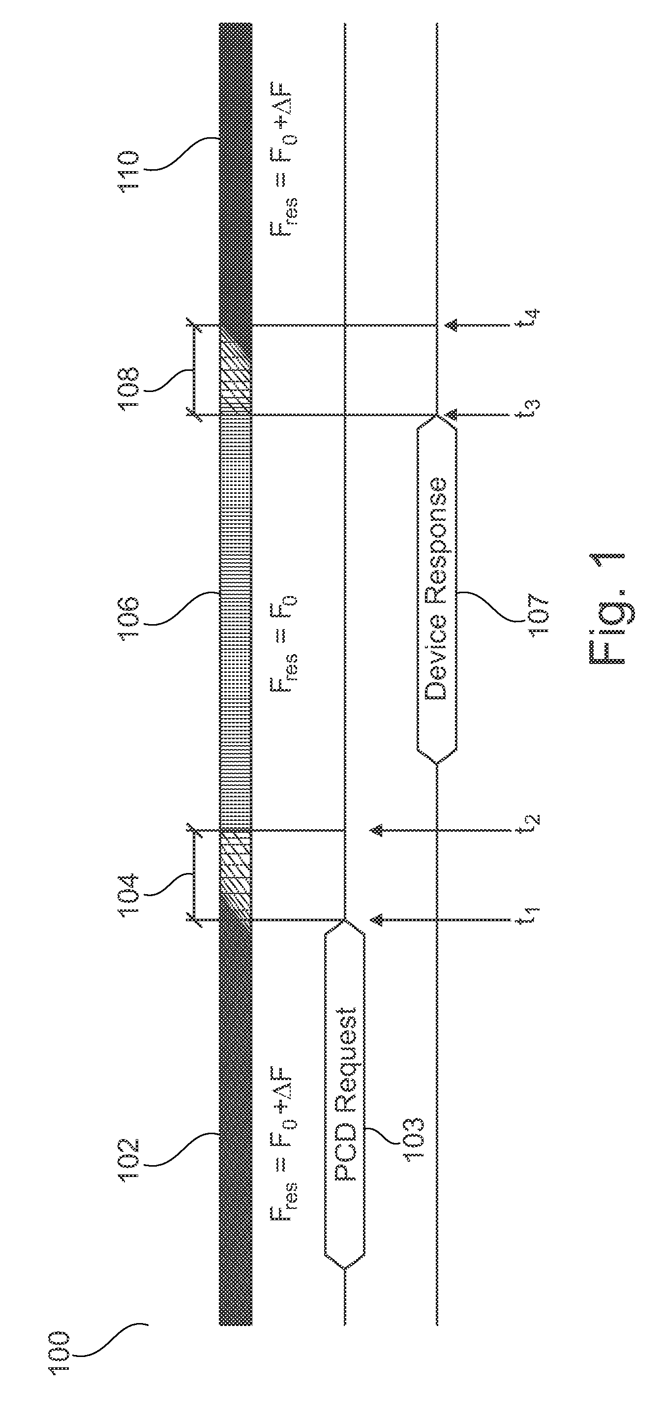
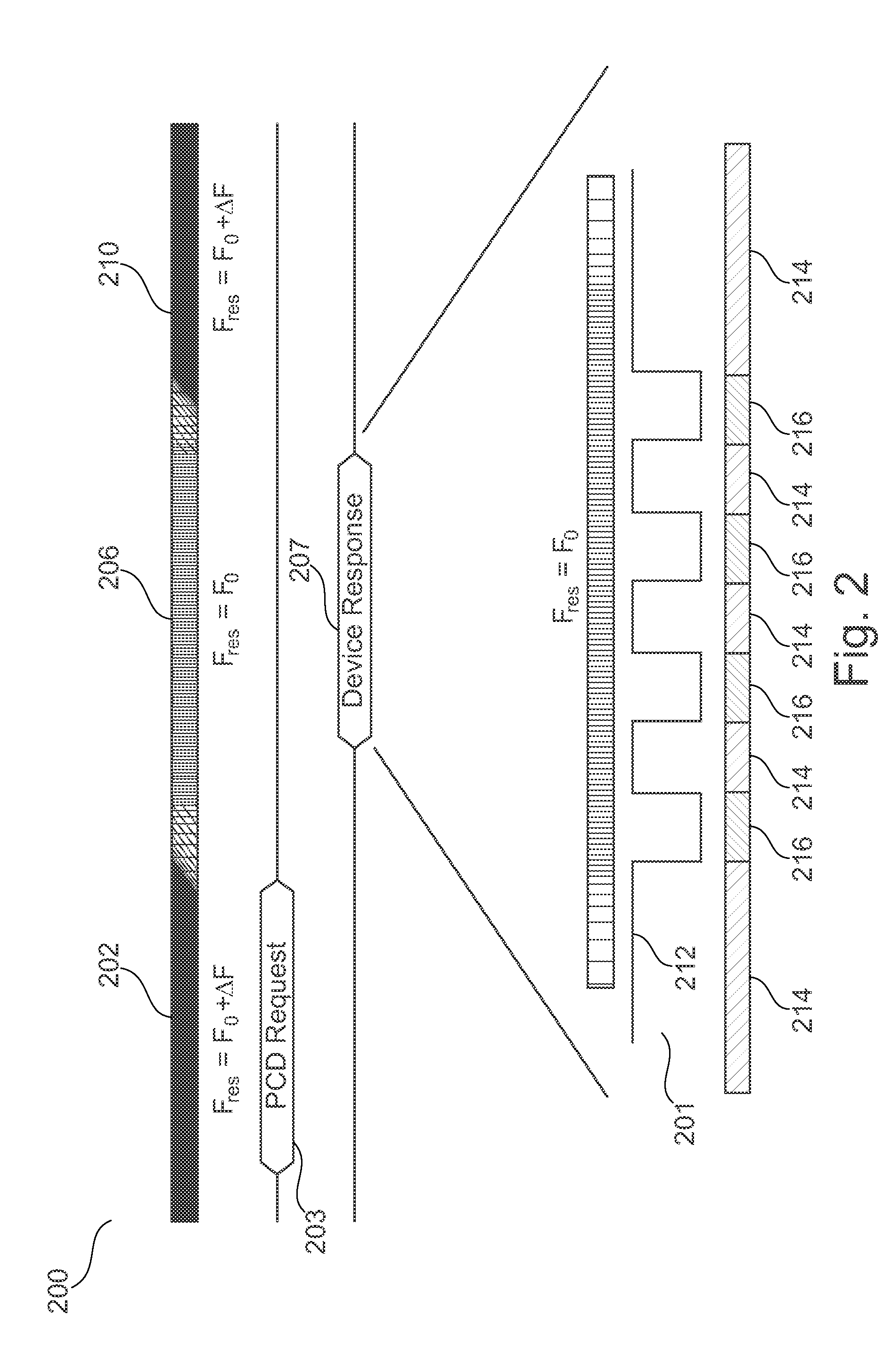
[0040]FIG. 1 shows a schematic overview 100 of bi-directional communication between an RF device and a reader / writer device in accordance with an embodiment. At this stage, the general principle of communication will be discussed. A specific example of a hardware configuration of an RF device is given below in conjunction with FIG. 3.

[0041]More specifically, the left-most part of FIG. 1 shows that an RF device is operating in a receiving mode during period 102. More specifically, the resonance frequency fres of the RF device's resonance circuit is set to f0+Δf, i.e. fres=f0+Δf. Here, f0 is the carrier frequency of a reader / writer device (not shown). During period 102, the RF device receives a request for transmission 103 from the reader / writer device. At ti...


PUM


Abstract

There is described an RF bidirectional communication device utilizing active load modulation, the device comprising (a) a resonance circuit including an antenna (326), and (b) a control unit (322) for controlling communication of the device, including switching between a transmission mode and a receiving mode, wherein the control unit is adapted to (c) modify a configuration of the resonance circuit such that the resonance circuit has a first resonance frequency (f0) when the device is in the transmission mode and a second resonance frequency (f0+Δf) when the device is in the receiving mode, and (d) modify the configuration of the resonance circuit such that a Q-factor of the resonance circuit is periodically decreased while the device is in the transmission mode. There is also described a corresponding method and a system comprising a RF device and a reader / writer device. Furthermore, there is described a computer program and a computer program product.

Description

FIELD OF THE INVENTION[0001]The present invention relates to the field of RF devices, in particular to RF devices for short range or contactless communication using active load modulation.ART BACKGROUND[0002]Recent RF devices, such as contactless transponder cards (e.g. Smartcards, e-Passports, Tickets, etc.) and NFC (Near Field Communication) devices, are capable of performing half-duplex bi-directional communication with a reader device. Thus, these RF devices are capable of operating in a receiving mode as well as in a transmitting mode. In the transmitting mode, RF devices may utilize active load modulation to transmit the information or data. In order to optimize the transmission, the antenna circuit of the RF device is tuned to the carrier frequency of the reader device, e.g. to 13.56 MHz in systems complying with ISO / IEC 14443 and NFC standards. However, such an antenna configuration is usually not ideal for use in the receiving mode, as the shape of the reader modulation may...

Claims


Application Information

Patent Timeline
IPC IPC(8): H04B1/44
CPCH04B1/44H04B5/24H04B5/48
Inventor PIEBER, MICHAELMERLIN, ERICHMENDEL, STEFAN
Owner NXP BV
Why Eureka
Try Eureka