Thermal Energy Storage Apparatus

a technology of energy storage and storage apparatus, which is applied in the direction of lighting and heating apparatus, indirect heat exchangers, heat storage plants, etc., can solve the problems of increasing gas pressure losses through the stores, increasing pressure drop, and poor thermal exchange, so as to increase the potential for pressure drop, increase the volume and horizontal cross-sectional area occupied by insulation, and increase the distance from the top of the store.

Inactive Publication Date: 2015-04-30
ENERGY TECH INST
View PDF12 Cites 61 Cited by
  • Summary
  • Abstract
  • Description
  • Claims
  • Application Information

AI Technical Summary

Benefits of technology

[0147]In the case of particulate material, the smaller and more densely packed the material, the greater the potential for pressure drops, and hence, the more desirable the use of layered stores (and flow regulation as described below), especially for particle sizes of 20 mm or less, or 10 mm or less, or even 7 mm or less.
[0148]Conveniently, the volume and horizontal cross-sectional area occupied by insulation may be s

Problems solved by technology

However, while these ‘irreversible’ thermal losses can be reduced by reducing the particle size, this increases gas pressure losses through the stores.
The one disadvantage is that there is a pressure drop associated with the fluid flow through the bed and this pressure drop increases significantly as the particle or pore size reduces.
Another problem associated with the p

Method used


Image

  • Thermal Energy Storage Apparatus
  • Thermal Energy Storage Apparatus
  • Thermal Energy Storage Apparatus

Examples


Embodiment Construction
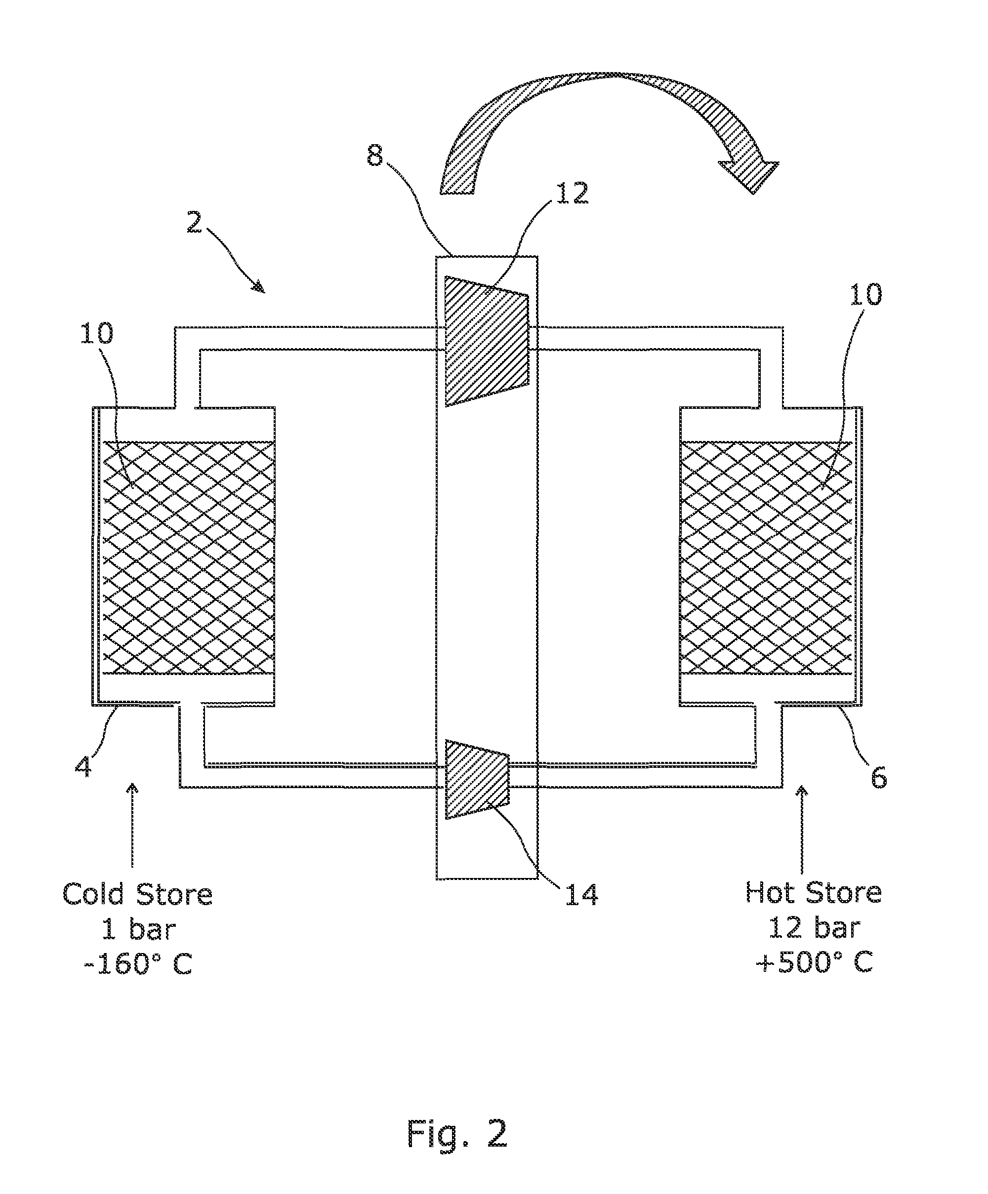
FIG. 2

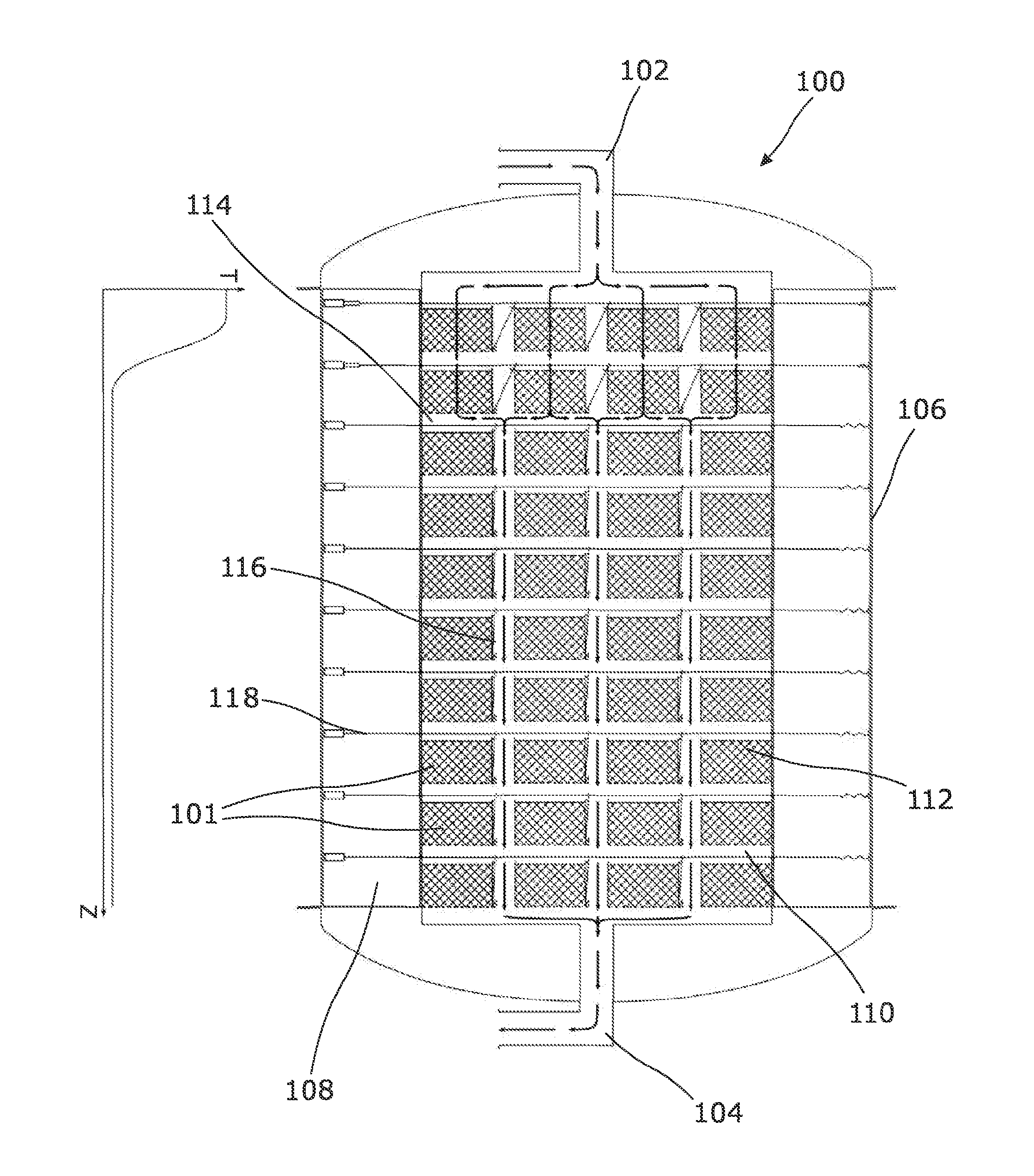
[0202]The present invention is directed towards improvements in thermal storage apparatus, and is particularly directed at heat stores for use in energy storage systems.

[0203]As explained above, FIG. 2 is a schematic of a PHES system such as is described in Applicant's earlier application, WO2009 / 044139. That system is more fully described below in order to demonstrate how hot and cold stores may operate in practice.

[0204]The system 2 is a reversible, closed cycle energy storage system operable in a charging mode to store electrical energy as thermal energy, and operable in a discharging mode to generate electrical energy from the stored thermal energy. The system comprises respective positive displacement devices 12 and 14, as well as a hot (high pressure) store 6 and a cold (lower pressure) store 4. During charging, device 12 compresses a gas and the hot, high pressure gas then passes through the hot store 6, where it gives up its heat, before being re-expanded in the other ...


PUM


Abstract

A thermal energy store comprising a chamber having a gas inlet and a gas outlet and a plurality of successive, downstream, gas permeable thermal storage layers disposed between them, each layer comprising gas permeable thermal storage media, the store being configured for gas flow from the gas inlet to gas outlet through the layers for transfer of thermal energy to or from the thermal storage media, wherein at least one of the layers is a valved layer provided with at least one valve operable selectively to allow or prevent at least some gas flow through that layer via the valve so as to bypass the thermal storage media. A control system may selectively alter the flow path of the gas flowing from inlet to outlet in response to the progress of a thermal front, so as to bypass thermal storage layers upstream of the thermal front, where transfer is complete, or downstream thereof, where transfer is minimal.

Description

TECHNICAL FIELD OF THE INVENTION[0001]The present invention relates to thermal energy storage apparatus, and methods of constructing and operating such apparatus. It also relates to systems incorporating such apparatus, including energy storage systems, and in particular, electricity storage systems such as, for example, Pumped Heat Electricity Storage (PHES) systems.BACKGROUND OF THE INVENTION[0002]In certain applications it is desirable to store either ‘heat’ or ‘cold’ in thermal energy storage apparatus (hereinafter referred to as a “heat store”) containing thermal storage media, which media is able to store the thermal energy efficiently until it is subsequently retrieved. The ‘heat’ or ‘cold’ is transferred to and from the thermal storage media by a fluid, normally a gas (e.g. an inert gas), that is in direct contact with the thermal storage media. The thermal storage media should have a high surface area to facilitate energy transfer, good porosity for gas flow, and a suitable...

Claims


Application Information

Patent Timeline
IPC IPC(8): F28D17/02
CPCF28D17/02F28D20/0056F28D2020/0065Y02E60/14F28D20/00
Inventor HOWES, JONATHAN SEBASTIANMACNAGHTEN, JAMESHUNT, ROWLAND GEOFFREYBENNETT, ROBERT GEOFFREYWILSON, ALEXANDER BRUCE
Owner ENERGY TECH INST
Why Eureka
Try Eureka