Electric latch retraction push-bar device

a push-bar device and latch technology, applied in the direction of fastening means, carpet fasteners, mechanical devices, etc., can solve the problems of failure, opportunity for device problems, and the same susceptibility to failure from wear of mechanical parts through the life of the device, so as to reduce the wear on the motor and surrounding assemblies, and save power

Active Publication Date: 2015-05-21
SECURITY DOOR CONTROLS
View PDF2 Cites 9 Cited by
  • Summary
  • Abstract
  • Description
  • Claims
  • Application Information

AI Technical Summary

Benefits of technology

[0012]The present invention provides an electric latch retraction push bar exit device that utilizes a motor to impart linear movement on the latch and to retract the latch. When the latch is retracted it is held in that position by a holding mechanism and the motor can be tu

Problems solved by technology

For example, retail stores use such secured doors in certain departments (such as, for example, the automotive department) which may not always be manned to prevent thieves from escaping through the door with valuable merchandise.
This causes the motor to overwork and produces a continuous drive to the motor which can ultimately burn it out.
This electronic monitoring or “rotation counting”

Method used


Image

  • Electric latch retraction push-bar device
  • Electric latch retraction push-bar device
  • Electric latch retraction push-bar device

Examples


Embodiment Construction

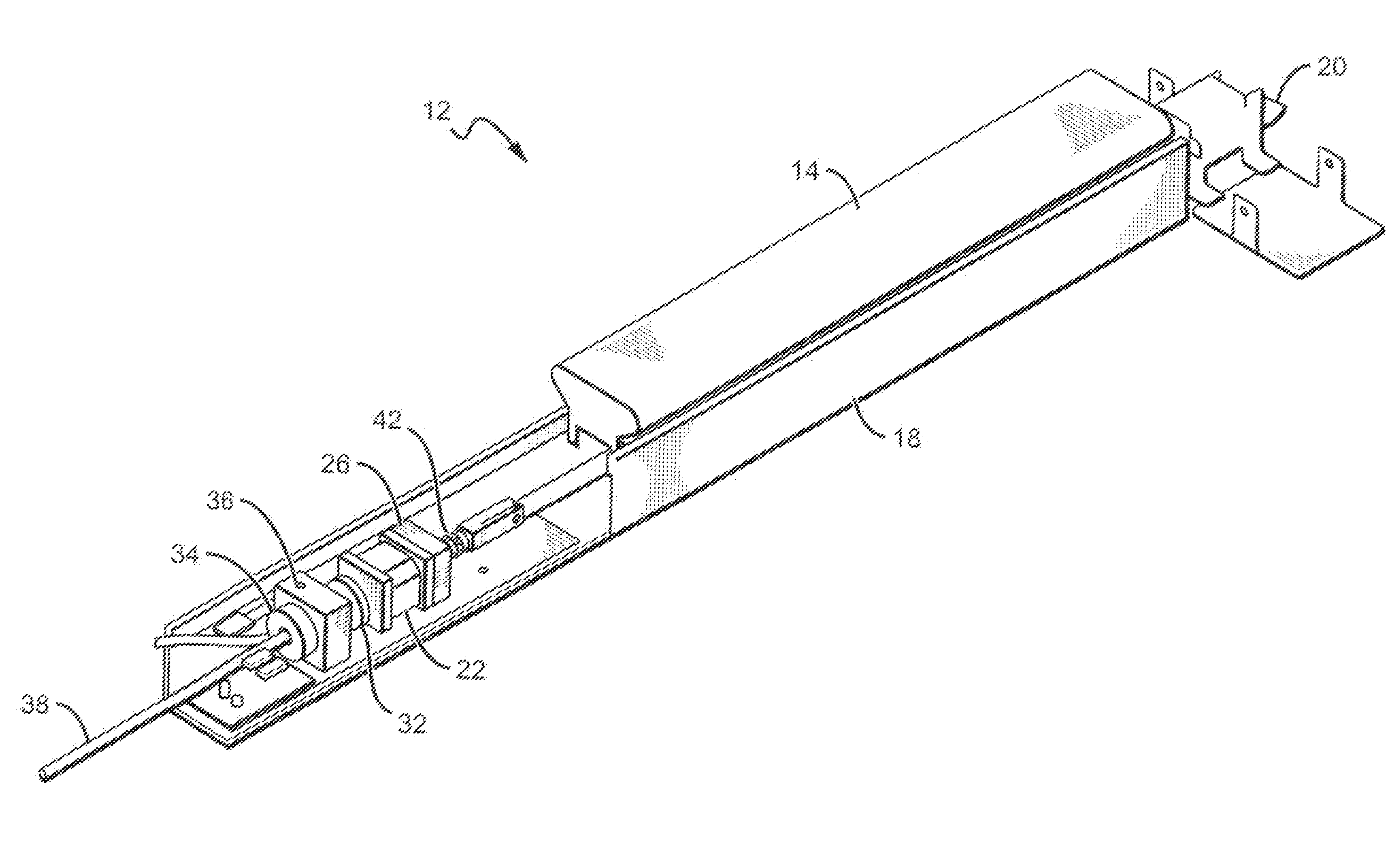
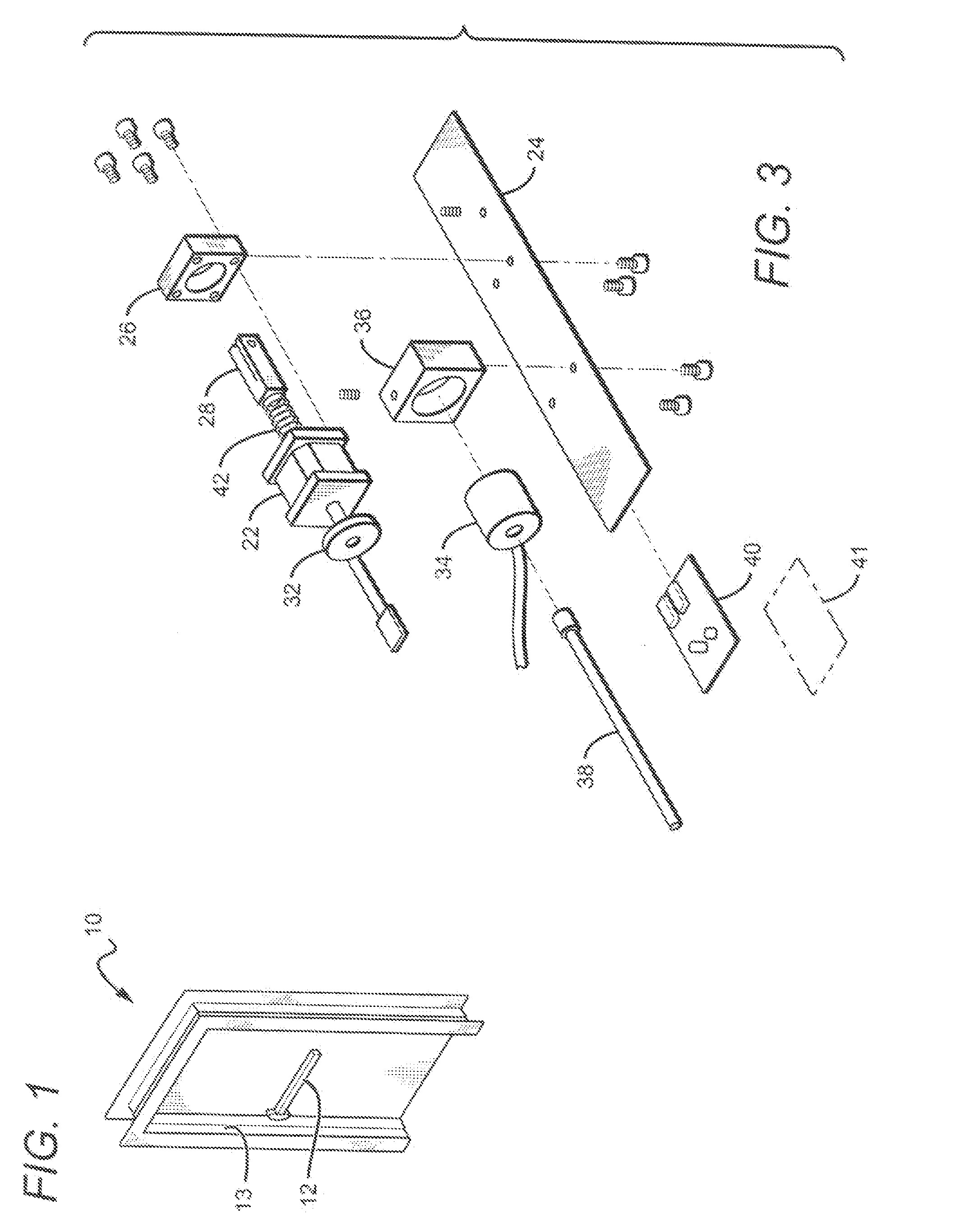
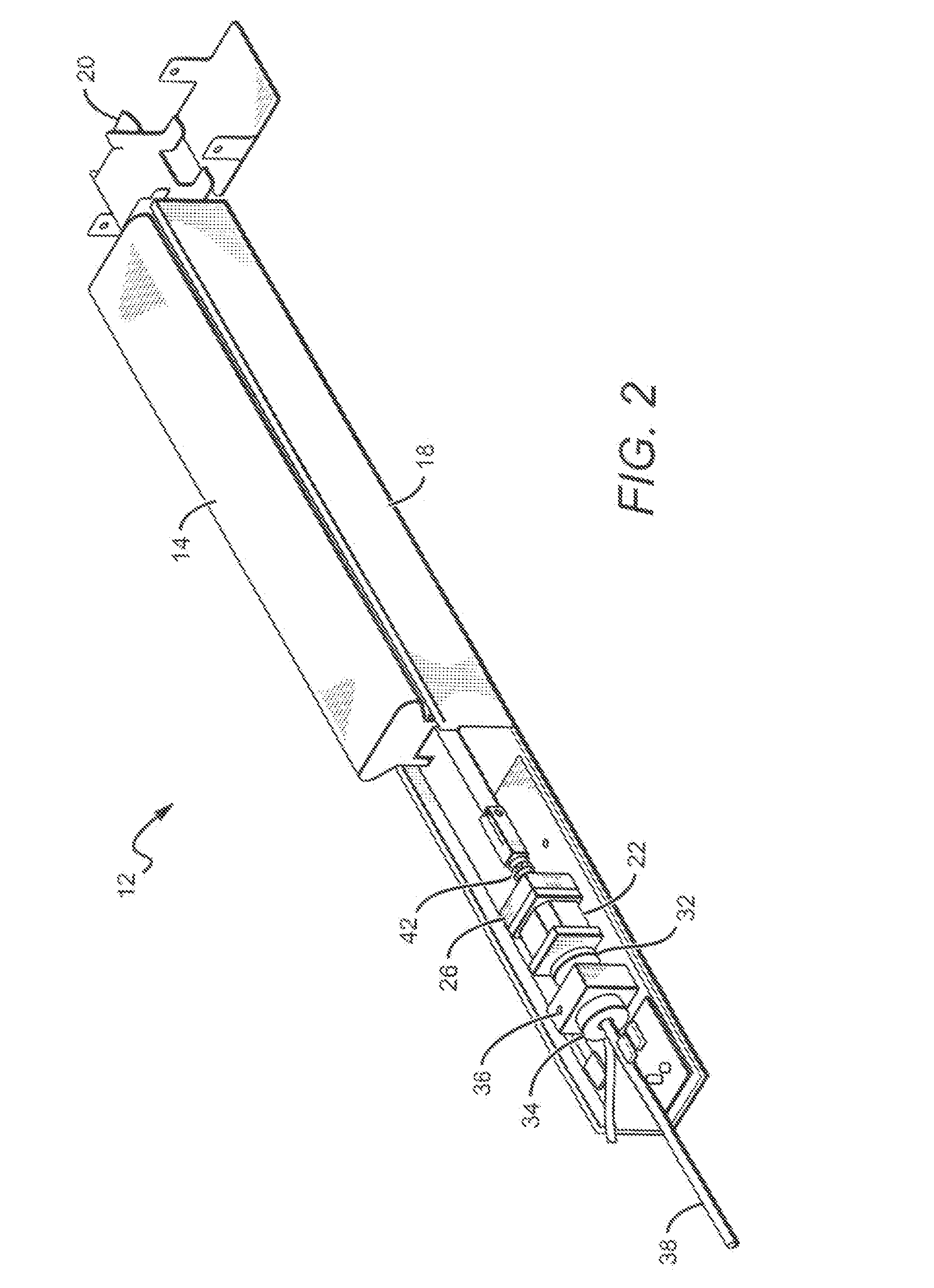
[0033]The present invention provides an electric latch retraction push-bar exit device (“push-bar exit device”) where the latch can be retracted through the standard pushing action on the push-bar. The exit devices according to the present invention can comprise secondary mechanisms for retracting the latch, such as through an electric motor. On some embodiments, the motor can be internal to the device housing and can comprise a stepper motor type linear actuator to retract the latch. When the actuator has moved to the retracted (unlatched) position, a holding magnet can be activated to hold the actuator in the unlatched position to allowing the motor to be switched off. Many different holding magnets can be used such as a magnetic holding coil.

[0034]Upon loss of power or when controller electronics remove power from the magnetic holding coil the actuator can be returned to the at-rest or latched position. In some embodiments biasing springs can be used to return the latch to the lo...


PUM


Abstract

An electric latch retraction device comprising a housing for receiving a plurality of internal components of the electric latch retraction device. An actuator mechanism is included in the housing, the actuator mechanism is adapted to impart linear movement on a latch, such that the latch is retracted towards the housing. A holding mechanism is also included in the housing, the holding mechanism holds the latch in a fully retracted position when the actuator is off. Other embodiments can comprise internal conversion mechanisms to convert the motor's linear motion to a different directional motion, with the different directional motion retracting the latch.

Description

[0001]This application is a continuation-in-part of and claims the benefit of U.S. patent application Ser. No. 14 / 469,915, to Geringer et al., filed Aug. 27, 2014, which is a continuation of, and claims the benefit of, U.S. patent application Ser. No. 12 / 616,564 to Geringer et al, filed on Nov. 11, 2009 (now U.S. Pat. No. 8,851,530), which claims the benefit of provisional application Ser. No. 61 / 199,560 to Geringer et al., filed on Nov. 17, 2008.BACKGROUND OF THE INVENTION[0002]1. Field of the Invention[0003]This invention relates to latch mechanisms for doors and in particular to door latch mechanisms comprising a latch retraction bar.[0004]2. Description of the Related Art[0005]Door locking mechanisms and security doors to prevent theft or vandalism have evolved over the years from simple doors with heavy duty locks to more sophisticated egress and access control devices. Hardware and systems for limiting and controlling egress and access through doors are generally utilized for ...

Claims


Application Information

Patent Timeline
IPC IPC(8): E05B47/00
CPCE05B47/0012E05B47/0006E05B47/023E05B63/0056E05B63/0065E05B65/1046E05B65/1053E05B65/1093E05B2047/0016E05B2047/0023E05B2047/0067Y10S292/65Y10T70/5159Y10T292/0908Y10T292/097Y10T292/1014Y10T292/1021Y10T292/1082Y10T292/11
Inventor GERINGER, ARTHUR V.GERINGER, DAVID A.
Owner SECURITY DOOR CONTROLS
Why Eureka
Try Eureka