Liquid distribution device

Active Publication Date: 2015-06-04
AMTPACIFIC
View PDF4 Cites 8 Cited by
  • Summary
  • Abstract
  • Description
  • Claims
  • Application Information

AI Technical Summary

Benefits of technology

[0020]The liquid distribution device according to the embodiment of the present invention is capable of continuously supplying the liquid in a constant ratio and of controlling the liquid in various ratios by automatically controlling the opening and closing of the valve.
[0021]According to the liquid distribution device according to the embodiment of the present invention, since a through-hole through which the supplied liquid passes is located at a predetermined height, the impurities in

Problems solved by technology

Therefore, for a time during which the feeder rotates from one side to the other side, the liquid is not continuously supplied, so that surging occurs and the performance of packing is decreased.
Also, since compressed air consumption is increased and durability is deteriorated due to the continuous rotation of the axis, the main parts should be replaced after operation for a certain per

Method used


Image

  • Liquid distribution device
  • Liquid distribution device
  • Liquid distribution device

Examples


Embodiment Construction

Technical Problem

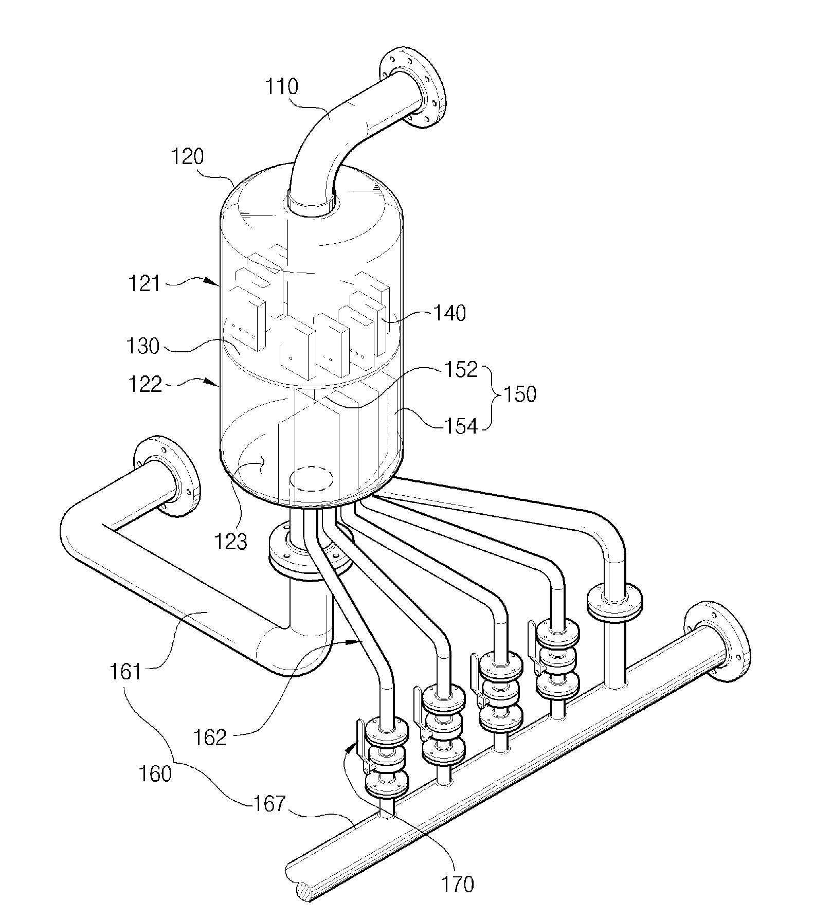
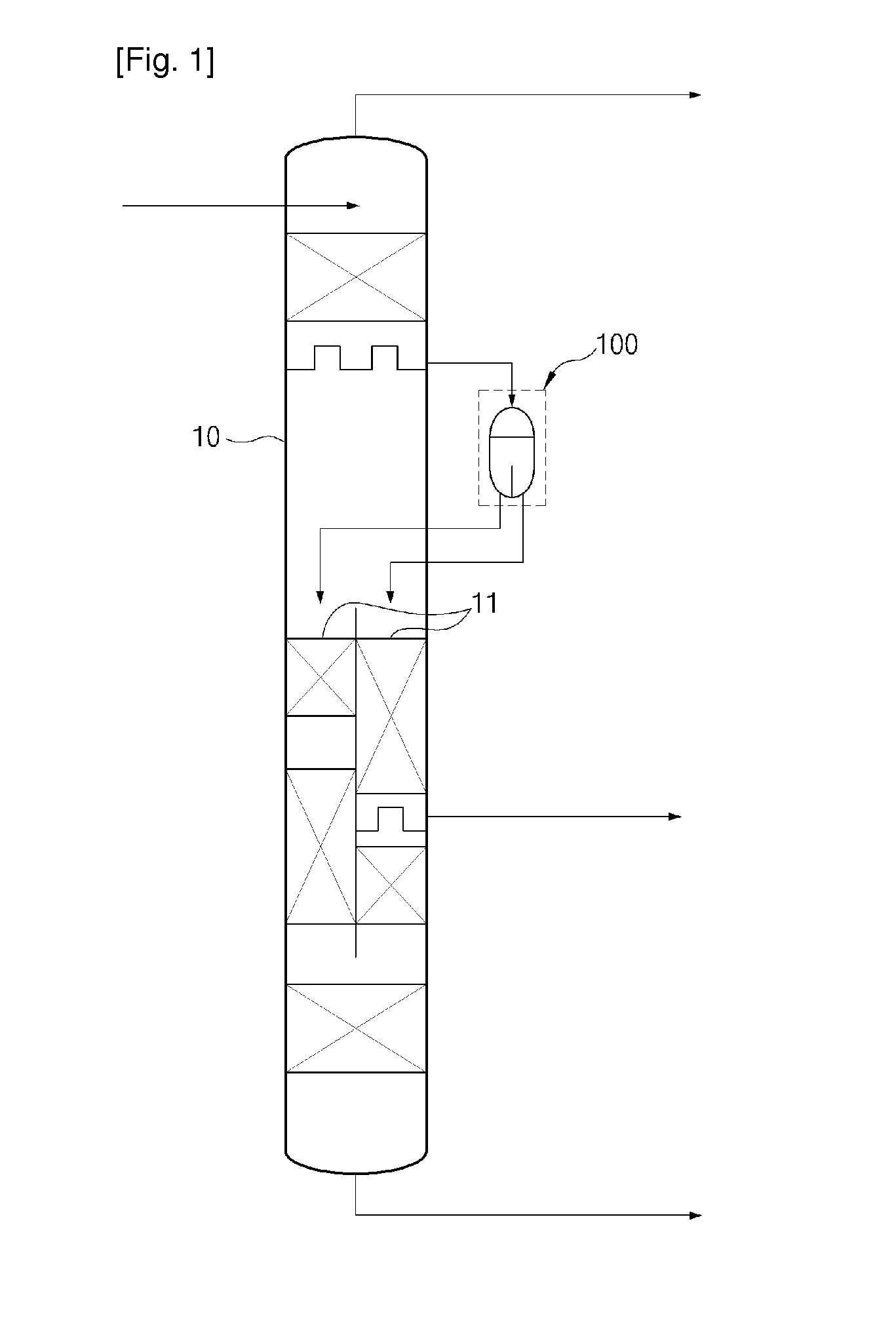
[0007]The present invention relates to a liquid distribution device capable of precisely controlling a supply ratio of liquid and continuously supplying the liquid in a constant ratio.

[0008]The liquid distribution device according to the embodiment of the present invention is capable of preventing the supply of the liquid from being stopped due to the impurities in the process of distributing the liquid in a constant ratio.

Technical Solution

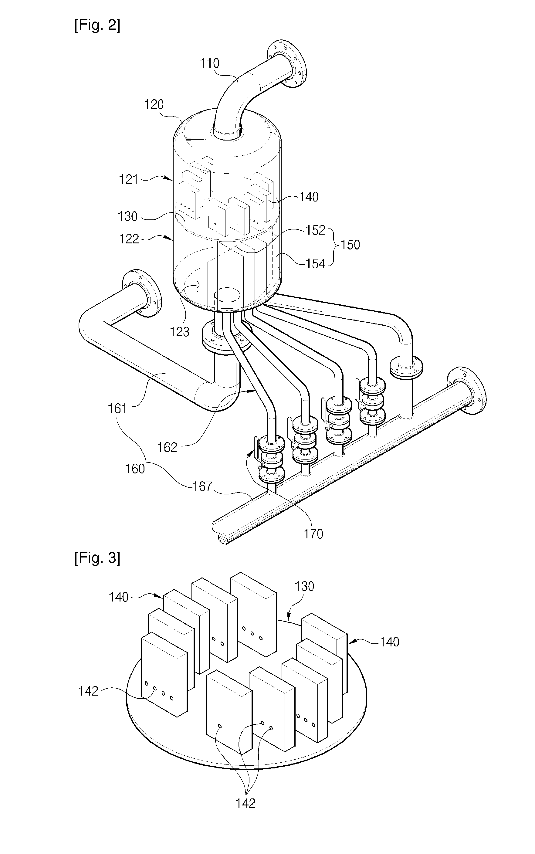
[0009]To achieve the above objective, the present invention provides a liquid distribution device that includes: a housing which provides a distribution space formed therein and receives liquid from an inlet pipe; a partition plate which is horizontally disposed within the housing and partitions the inner space of the housing into an upper space and a lower space, a top surface of the partition plate being divided into a first partition portion and a second partition portion which have different liquid distribution degrees; a ris...


PUM


Abstract

The present invention is capable of precisely controlling a supply ratio of liquid and continuously supplying liquid at a constant rate by using partition plates for controlling the amount of liquid distribution.

Description

TECHNICAL FIELD[0001]The present invention relates to a liquid distribution device, and more particularly to a liquid distribution device capable of precisely controlling a supply ratio of liquid and continuously supplying the liquid in a constant ratio.BACKGROUND OF INVENTION[0002]In general, a liquid distribution device is used in petroleum refinery, petrochemistry and fine chemistry, and is used in a scrubber, an absorber, etc., which adopt the principles of distillation, absorption and cooling so as to remove harmful gases or organic matters.[0003]There is a column which is currently industrially used in distillation, absorption, and cooling and separates the desired material through gas-liquid contact. Recently, a divided wall column is used to save energy and reduce the investment cost. The divided wall column has a structure formed by combining two columns into one. The divided wall column is required to distribute the liquid in the upper portion thereof to lower two divided ...

Claims


Application Information

Patent Timeline
IPC IPC(8): G05D11/00
CPCG05D11/003B01D3/008B67D7/78B01J4/005B01J4/008B01J4/02Y10T137/87877Y10T137/4857Y10T137/86212Y10T137/87539Y10T137/479Y10T137/87547Y10T137/85938B01D3/32B01J4/00B67D99/00B01D3/141B01D53/185
Inventor LEE, BYEONG KYEOMKIM, KWANG HYUN
Owner AMTPACIFIC
Why Eureka
Try Eureka