Medical balloon for a catheter

a technology of medical balloons and catheters, applied in balloon catheters, medical science, ear treatment, etc., can solve the problems of local flow constriction or damage of natural conduits in the body, unfavorable foreshortening effect, and length deviation, and achieve the effect of improving expansion properties

Active Publication Date: 2015-06-25
ABBOTT LAB VASCULAR ENTERPRISE
View PDF2 Cites 0 Cited by
  • Summary
  • Abstract
  • Description
  • Claims
  • Application Information

AI Technical Summary

Benefits of technology

[0006]It is an object of the present invention to pr

Problems solved by technology

In medicine, a natural conduit in a body may be locally flow constricted or damaged.
This foreshorte

Method used


Image

  • Medical balloon for a catheter
  • Medical balloon for a catheter
  • Medical balloon for a catheter

Examples


Embodiment Construction

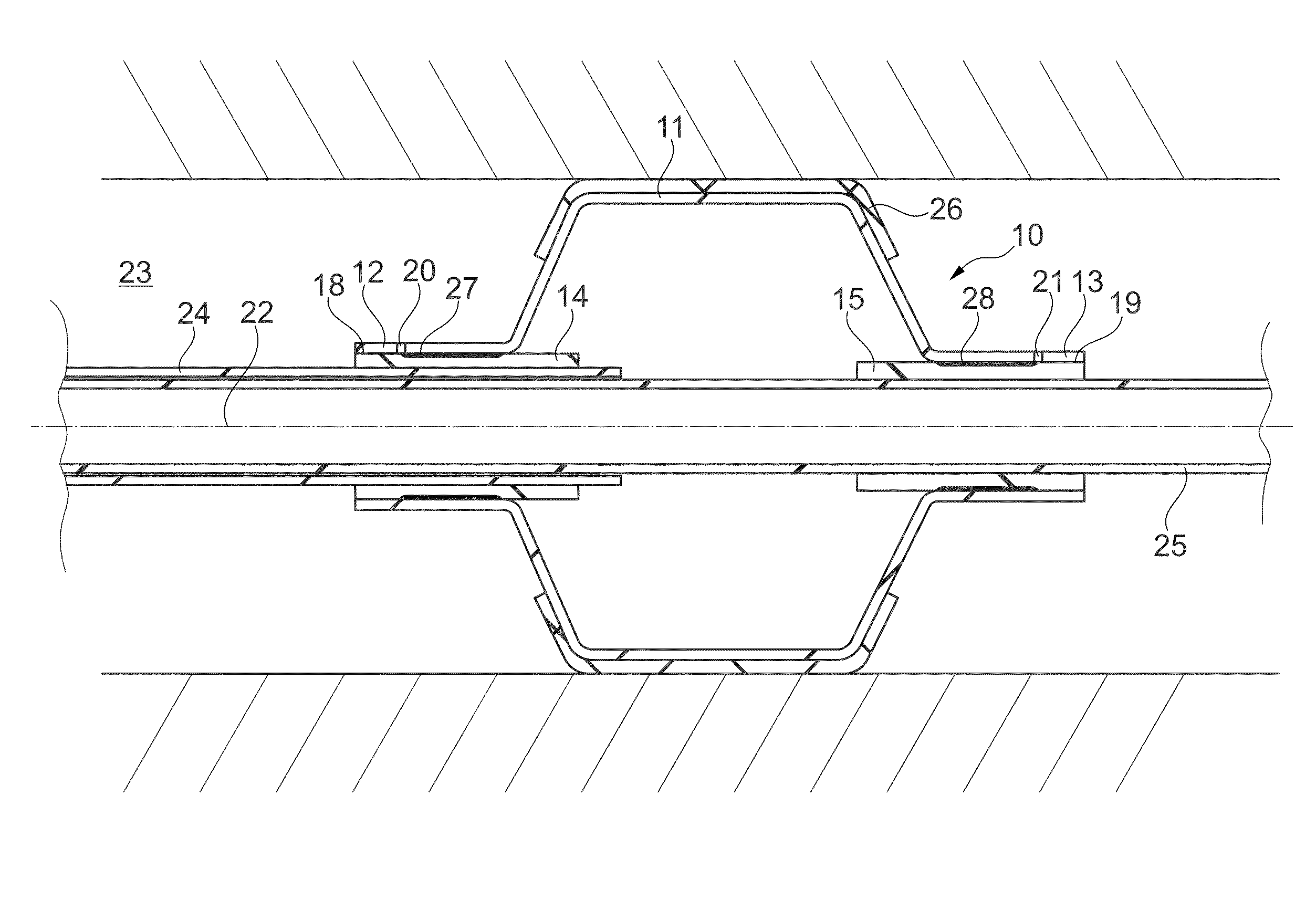
[0029]FIG. 3 schematically illustrates a medical balloon 10 (or simply referred to as “balloon”) according to an exemplary embodiment of the invention. FIG. 4 schematically illustrates part of the balloon 10 in a three-dimensional view. The balloon 10 can be formed in numeral different shapes, such as a conical balloon, a spherical balloon, a long spherical balloon, an offset balloon, a square balloon, a tapered balloon, a stepped balloon, etc. FIG. 3 illustrates as one example a balloon 10 having a central section 11 which is cylindrical shaped in a fully expanded state (shown in FIG. 6). The portions of the balloon 10 at both longitudinal ends of the central section 11, are a proximal cone section 29 and a distal cone section 30, both of which have a cone shape in the fully expanded state of the balloon, which state is illustrated in FIG. 6. The terms “proximal” and “distal” are well known in connection with catheters, wherein “distal” refers to the end of the catheter which is in...


PUM

PropertyMeasurementUnit
Pressureaaaaaaaaaa

Abstract

A medical balloon for deployment of stents is disclosed. The medical balloon includes a central section; a proximal and a distal cone section; a proximal and a distal shaft section; a proximal sleeve which is arranged coaxial to and radially inside the proximal shaft section. The proximal end of the proximal shaft section is permanently connected and/or unitarily formed with the proximal end of the proximal sleeve, and distal thereto, at least part of the proximal cone section is connected with the proximal sleeve by an adhesive bond, and a distal sleeve which is arranged coaxial to and radially inside the distal shaft section. Methods of manufacturing a medical balloon are disclosed.

Description

CROSS REFERENCE TO RELATED APPLICATIONS[0001]This application claims priority to European Patent Application No. 13198915.4, filed on Dec. 20, 2013, the entirety of which is incorporated herein by reference.[0002]The invention relates to a medical balloon for a catheter, a catheter having such a balloon and a method for manufacturing such a balloon.BACKGROUND OF THE INVENTION[0003]In medicine, a natural conduit in a body may be locally flow constricted or damaged. A stent or stent graft may be inserted into this natural conduit, in order to counteract such a flow constriction or to repair damage. Stents may be deployed by means of a balloon catheter. The stent is crimped around the balloon before deployment, the catheter is introduced into a body lumen and once the balloon is positioned appropriately, the balloon is inflated and expands the stent.[0004]FIGS. 1a to 1d illustrate a few exemplary chronologic steps of inflating a balloon from the state of the art. The balloon shown in t...

Claims


Application Information

Patent Timeline
IPC IPC(8): A61M25/10A61F2/958
CPCA61M25/1025A61F2/958A61M25/1034A61F2220/0058A61M2025/1059A61F2220/005A61M25/1002A61M25/104Y10T156/1005
Inventor GRANDT, AXEL
Owner ABBOTT LAB VASCULAR ENTERPRISE
Why Eureka
Try Eureka