Method and Node for Interference Measurement via inter-Cell Cooperation

a technology of inter-cell cooperation and interference measurement, applied in the field of communication, can solve problems such as resource configuration conflict, relatively severe interference between cells, and new problems, and achieve the effect of accurate resource scheduling

Inactive Publication Date: 2016-04-21
XIAN ZHONGXING NEW SOFTWARE
View PDF0 Cites 40 Cited by
  • Summary
  • Abstract
  • Description
  • Claims
  • Application Information

AI Technical Summary

Benefits of technology

[0081]With the embodiment of the present invention, the cells can obtain the interference measurement resource configuration used for an accurate interference measurement to avoid conflicts of interference measurement resource configuration between the cells; through the indicators of the expected downlink reference signal to the downlink service EPRE ratio, the cell can obtain the expected interference information of the adjacent cells; by exchanging more accurate quantifiable interference level information, the cells can perform a more accurate resource scheduling to avoid the inter-cell interference.

Problems solved by technology

Because the distance between the base stations is small, interference between the cells can be relatively severe.
However, when coordinating between cells connected via the non-ideal backhaul link, it needs to rely on the X2 interface to perform the coordinated information exchange.
In the non-ideal backhaul link, centralized and decentralized inter-cell coordinated information transmission brings some new problems.
In the case that respective base stations are not configured with global measurement resources, it may have the problem of resource configuration conflicts.
Moreover, due to the delay problem of non-ideal backhaul link, the Pc transfer needs to more accurately reflect the interference situation of the adjacent cell shared channel at different time points or in different frequency resources.
But when using the downlink power control as the interference avoidance method, the uplink or downlink HII and OI simply indicate the interference level information, such as, “high interference”, “medium interference” and “low interference”, “high interference sensitive”, “medium interference sensitive” or “low interference sensitive”, and it cannot meet the more accurate downlink power control coordinated information exchanging needs.
Through the abovementioned indicator, the adjacent cells cannot obtain quantifiable indicator, such as, what SINR value can be considered as “high interference”, therefore it is inconvenient for the adjacent cells to perform the more accurate adjustment of transmitting power.

Method used


Image

  • Method and Node for Interference Measurement via inter-Cell Cooperation
  • Method and Node for Interference Measurement via inter-Cell Cooperation
  • Method and Node for Interference Measurement via inter-Cell Cooperation

Examples


first application example

The First Application Example

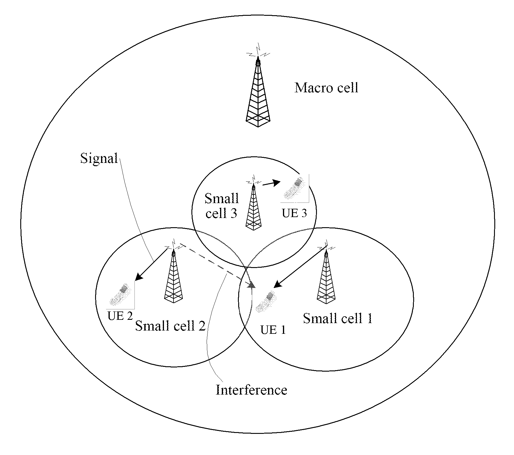
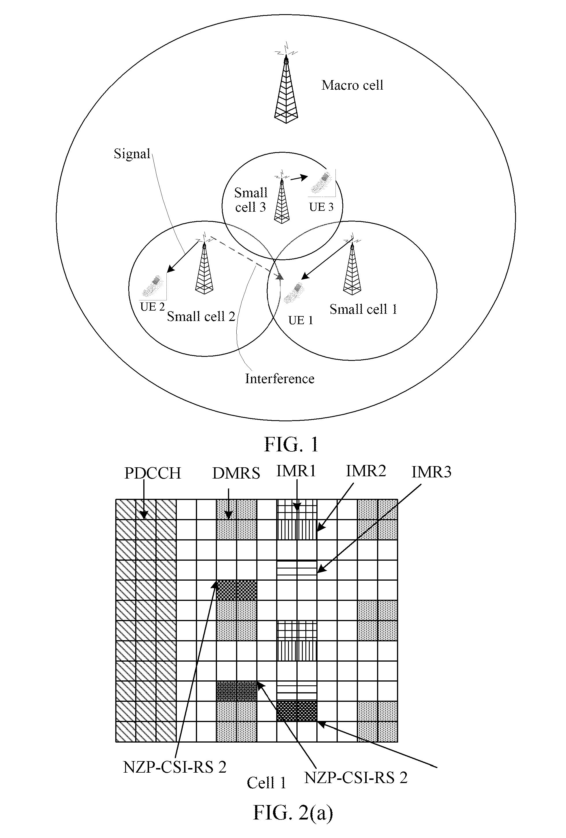
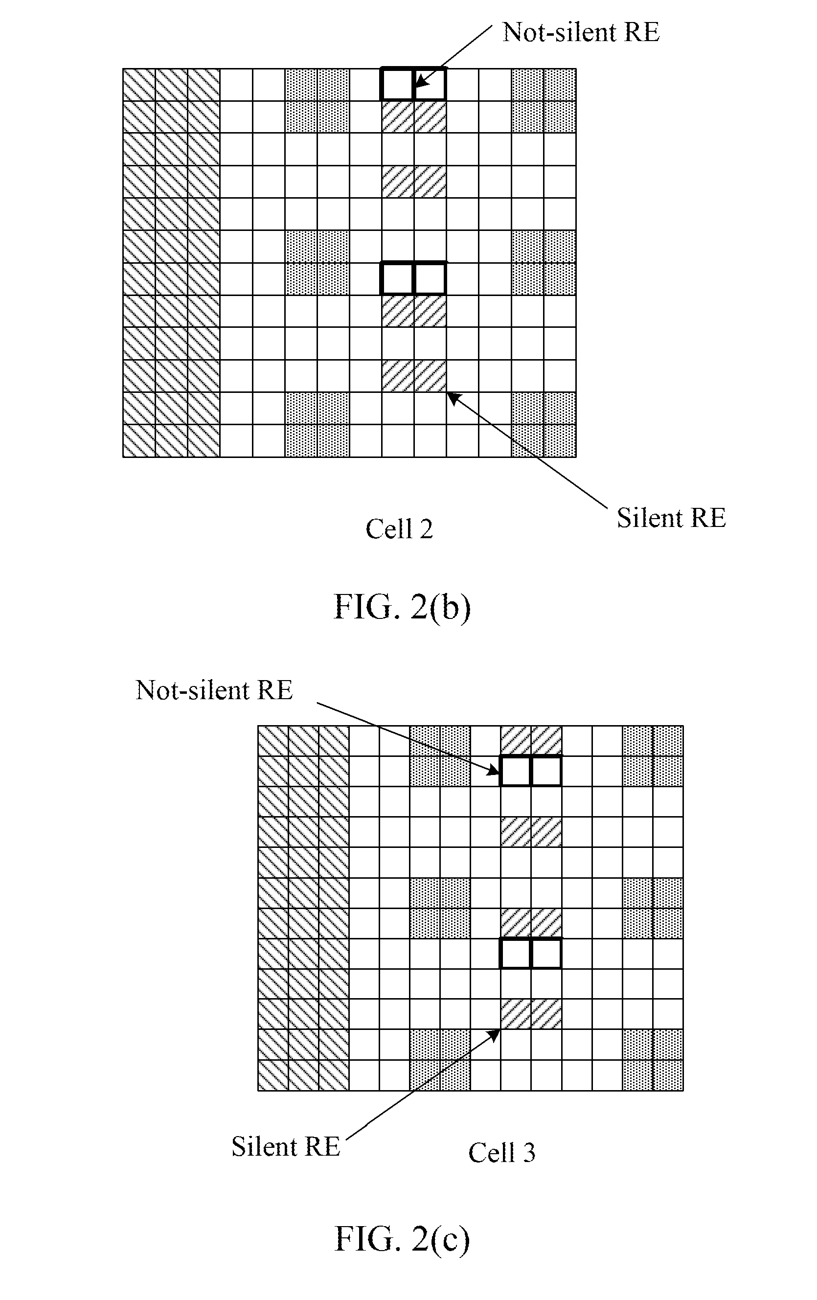
[0100]As shown in FIG. 1 and FIGS. 2 (a), 2 (b) and 2 (c), it is assumed that the macro cell and the small cell in FIG. 1 use different carriers, and the small cells 1, 2 and 3 form into one cell cluster, and the base stations to which respective small cells belongs are close to each other and form into one coordinated set. The small cell 1 uses the interference measurement resource to respectively perform interference measurements in the two cases of shutting down the small cell 2 and shutting down the small cell 3. As shown in FIG. 5, the small cell 1 respectively takes the corresponding interference measurement resource information (IMR information) from the small cell 2 and the small cell 3, and perform the interference measurement on the Confirmed interference measurements resource (confirmed IMR). Both the small cell 3 and the small cell 2 has one list of coordinated cells, and this list may be obtained via the inter-base-station measurement, or by...

second application example

The Second Application Example

[0106]Different from the first application example, before the base station to which the small cell 1 belongs needs to obtain contents of the small cell 2 and small cell 3, including the interference measurement resource being in use, resources configured as the ZP-CSI-RS, or the RE locations at which they are being measured by the other nodes, it respectively sends a request to the small cell 2 and the small cell 3, and then the small cell 2 and the small cell 3 send the small cell 1 contents including the respective interference measurement resources being in use, resources configured as the ZP-CSI-RS or RE locations at which they are being measured by the other nodes and so on. The other procedures are the same as the above-mentioned first application example and will not be repeated here.

third application example

The Third Application Example

[0107]Different from the first and second application examples, in the present application example, base station to which the small cell 1 belongs or the UE within its serving range obtains the interference measurement resource information by measuring the NZP-CSI-RS of the adjacent cells. The small cells 2 and 3 respectively notify the small cell 1 of the configuration information of NZP-CSI-RS 2 and NZP-CSI-RS 3 (as shown in FIG. 2 (a), 2 (b), 2 (c)) as well as their corresponding ratios Pc2 and Pc3 of PDSCH EPRE to NZP-CSI-RS power (take the small cell 2 as an example, the specific manner is shown in FIG. 6). Wherein, Pc2 and Pc3 are expected power ratios used by the cells 2 and 3. The frequency domain range indicated by each Pc is the corresponding bandwidth of the UE performing the CSI feedback of wideband.

[0108]Take the manner of the UE1 measuring and reporting the interference measurement resource information for example, the UE1 obtains the recei...


PUM


Abstract

Disclosed are an inter-cell coordinated interference measurement method and node, wherein, the method is applied to each node performing a coordinated interference measurement, and includes: receiving first measurement resource information transmitted by other network nodes via a backhaul link to a present node for coordinated interference measurement; determining second measurement resource information used by the present node for interference measurement according to the first measurement resource information transmitted by the coordinated network nodes, and instructing relevant coordinated network nodes to correspondingly configure a resource in accordance with the second measurement resource information of the present node; wherein the second measurement resource includes an interference measurement resource and / or a channel state information reference signal (CSI-RS); and performing interference measurement on the second measurement resource.

Description

TECHNICAL FIELD[0001]The present document relates to the field of communications, and more particularly, to an inter-cell coordinated interference measurement method and node.BACKGROUND OF THE RELATED ART[0002]In order to increase the data throughput of edge users having relatively large inter-cell interference in the cellular network, the study in the Long Term Evolution (referred to as LTE) system R12 proposed the small cell technology which increases the capacity of wireless networks by adding a lot of low-power base stations. These wireless networks can be densely distributed in a certain area to form a cluster, and cells within one cluster may be connected via a non-ideal backhaul link. Because the distance between the base stations is small, interference between the cells can be relatively severe.[0003]As the scenario shown in FIG. 1, there are three co-frequency adjacent small cells 1, 2 and 3 in the coverage of macro cell. The user equipment 1 (UE1) under the small cell 1 is...

Claims


Application Information

Patent Timeline
Patent Type & Authority Applications(United States)
IPC IPC(8): H04L5/00H04W72/04H04W52/24H04W72/08
CPCH04L5/0073H04W72/082H04W52/243H04W72/0453H04L5/0048H04W72/0446H04W24/10H04L5/0051H04W72/541
Inventor ZHENG, YONGLI, YU NGOKSUN, YUNFENG
Owner XIAN ZHONGXING NEW SOFTWARE
Why Eureka
Try Eureka