Pwm rectifier including capacitance calculation unit

a capacitance calculation and rectifier technology, applied in resistance/reactance/impedence, power supply testing, instruments, etc., can solve the problems of harmonics or reactive power of power lines, ripple current flowing through dc links, increasing dc voltage fluctuation, etc., to achieve accurate measurement of the capacitance of smoothing capacitors

Active Publication Date: 2017-04-06
FANUC LTD
View PDF0 Cites 8 Cited by
  • Summary
  • Abstract
  • Description
  • Claims
  • Application Information

AI Technical Summary

Benefits of technology

[0019]In consideration of the above-described problems, an object of the present invention is to provide a small and low-cost PWM rectifier that is capable of accurately measuring the capacitance of a smoothing capacitor which is connected to the DC output side in parallel.

Problems solved by technology

A rectifier using a diode rectification method has an advantage of low price but also has a disadvantage that power line harmonics or reactive power increases.
When the capacitance of the smoothing capacitor 5 decreases, a problem is caused in that a ripple current which flows through the DC link increases and fluctuation of the DC voltage grows.
If it is not possible to measure the capacitance of the smoothing capacitor accurately, timing for the replacement of the smoothing capacitor may be missed and a substantial ripple current and DC voltage fluctuation may be caused to the DC link.
Alternatively, a case in which a smoothing capacitor which has not reached the end of a lifespan thereof is replaced unnecessarily may be caused.
For example, since, in the invention disclosed in Japanese Unexamined Patent Publication No. 05-76180, the capacitance of the smoothing capacitor to be estimated depends on the peak value of the AC voltage on the AC power supply side and the resistance value of the charging resistor, it is not possible to measure the capacitance of the smoothing capacitor accurately when the peak value of the AC voltage and the resistance value of the charging resistor contain errors.
For example, according to the invention disclosed in International Publication No. 2010 / 055556, although, when the AC power supply is a single-phase AC power supply, no substantial error is caused even if the inflowing current to the smoothing capacitor is approximated to the absolute value of the AC current on the AC power supply side, such an approximation is not possible when the AC power supply is a three-phase AC power supply and it is thus not possible to know the inflowing current to the smoothing capacitor accurately.
Although it may be possible to calculate the capacitance of the smoothing capacitor accurately by disposing a DC current detection unit at the preceding stage or the succeeding stage of an initial charging circuit and measuring the inflowing current to the smoothing capacitor, newly disposing the DC current detection unit leads to an increase in cost and space.

Method used


Image

  • Pwm rectifier including capacitance calculation unit
  • Pwm rectifier including capacitance calculation unit
  • Pwm rectifier including capacitance calculation unit

Examples


Embodiment Construction

[0031]A PWM rectifier including a capacitance calculation unit will be described below with reference to the accompanying drawings. However, it should be understood that the present invention is not limited to the drawings or embodiments which will be described below.

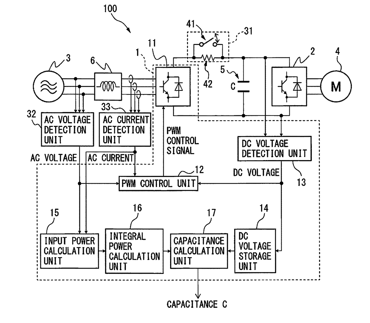
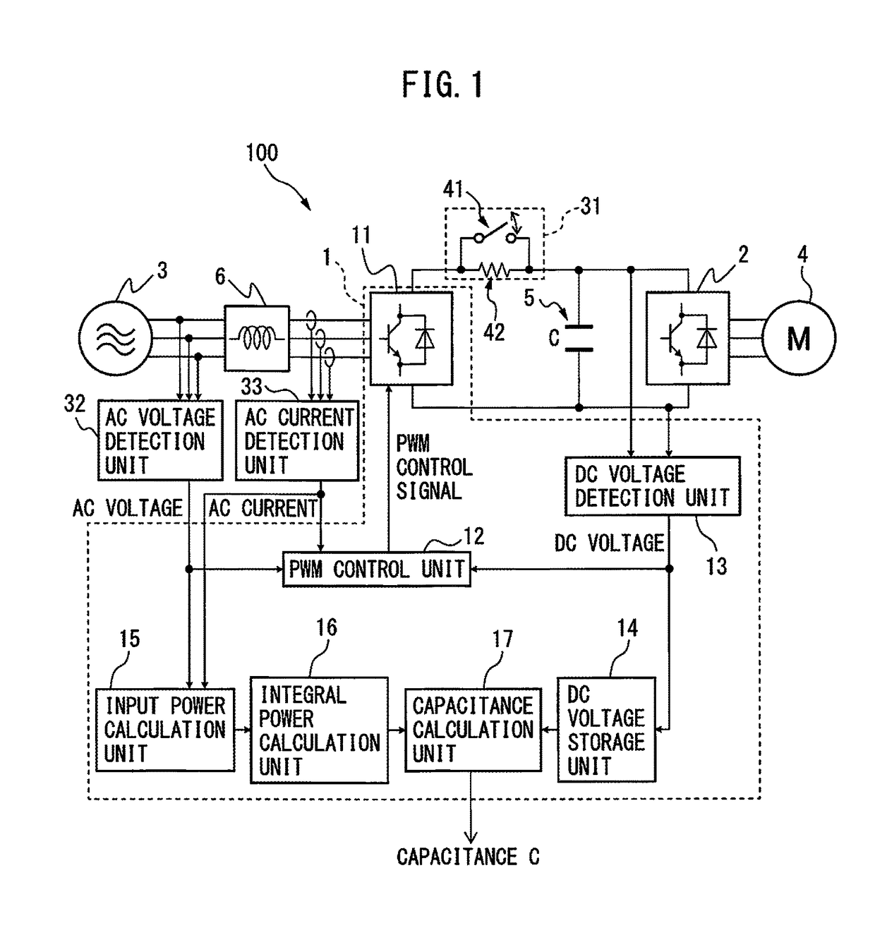
[0032]In the following description, a case in which a PWM rectifier is disposed in a motor control device which is connected to an inverter through a DC link having a smoothing capacitor will be described as an embodiment. However, the PWM rectifier is not particularly limited to use as a rectifier in a motor control device, and the PWM rectifier may be applied to any device that has a configuration in which a PWM rectifier and an inverter are connected through a DC link having a smoothing capacitor. A load connected to the configuration is also not particularly limited to a motor.

[0033]FIG. 1 is a principle block diagram illustrating a PWM rectifier according to an embodiment. A motor control device 100 includes a PWM ...


PUM


Abstract

A PWM rectifier includes a main circuit unit carrying out AC-DC power conversion by PWM-control, a PWM control unit PWM-controlling the main circuit unit, a DC voltage detection unit detecting a DC voltage across a smoothing capacitor connected to the DC-side of the main circuit unit, a DC voltage storage unit storing respective DC voltages at the start and end times of an initial boost period during which the smoothing capacitor having been charged to an AC voltage peak value is further charged to a higher voltage, an input power calculation unit calculating input power flowing in from the AC-side based on an AC voltage and current, an integral power calculation unit calculating integral power from the input power over the initial boost period, and a capacitance calculation unit calculating the capacitance of the smoothing capacitor based on the respective DC voltages and the integral power.

Description

RELATED APPLICATIONS[0001]The present application is a continuation of U.S. application Ser. No. 14 / 849,056, filed Sep. 9, 2015, which claims priority to Japanese Application Number 2014-184549, filed Sep. 10, 2014. The disclosures of the above-listed applications are hereby incorporated by reference herein in their entirety.FIELD OF THE INVENTION[0002]The present invention relates to a PWM rectifier that converts AC power to DC power by controlling a switching element using a PWM signal (pulse width modulation signal).DESCRIPTION OF THE RELATED ART[0003]A motor control device for driving a motor in a machine tool, an industrial machine, a forming machine, an injection molding machine, or various types of robots uses AC power, to which AC power input from the AC power supply side is once converted to DC power and the DC power is further converted, as drive power of a motor attached to each drive shaft is known. A motor control device includes a rectifier configured to rectify AC pow...

Claims


Application Information

Patent Timeline
Patent Type & Authority Applications(United States)
IPC IPC(8): H02M7/217H02M5/458G01R15/16H02M1/12H02P27/08H02M1/08H02M1/42
CPCH02M7/217H02M1/08H02M5/458H02M2001/0009H02M1/12H02P27/08G01R15/16H02M1/4225G01R31/40G01R27/26H02M1/32H02M7/219H02M5/4585H02M7/2173
Inventor NIWA, MASAKAZU
Owner FANUC LTD
Why Eureka
Try Eureka